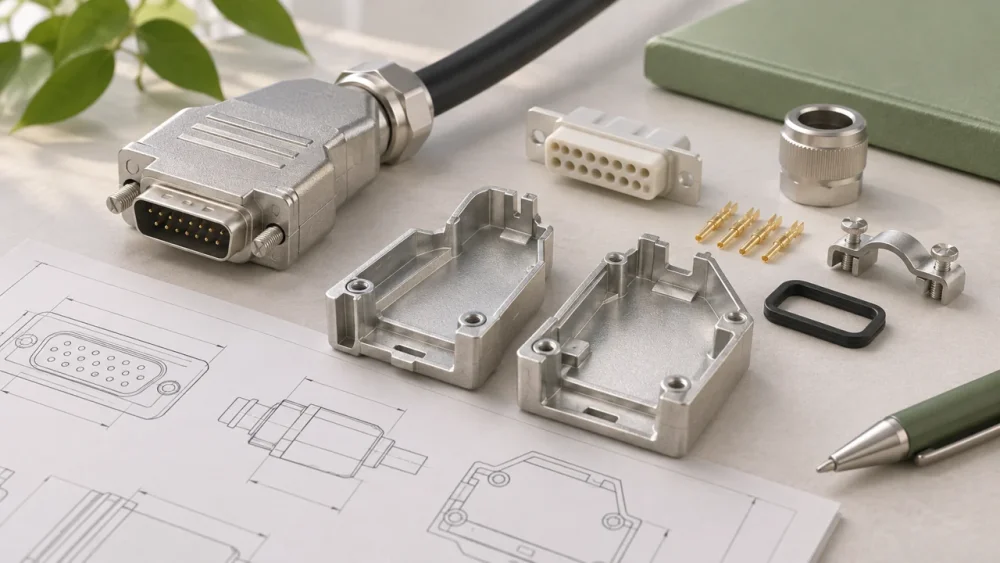
Custom Zinc Die Cast Connector Shells for Cable Assemblies
Discuss zinc die cast connector shells and backshells. Define mating geometry, cable entry, conductive surfaces and the metal-part supply boundary.
Discuss your requirements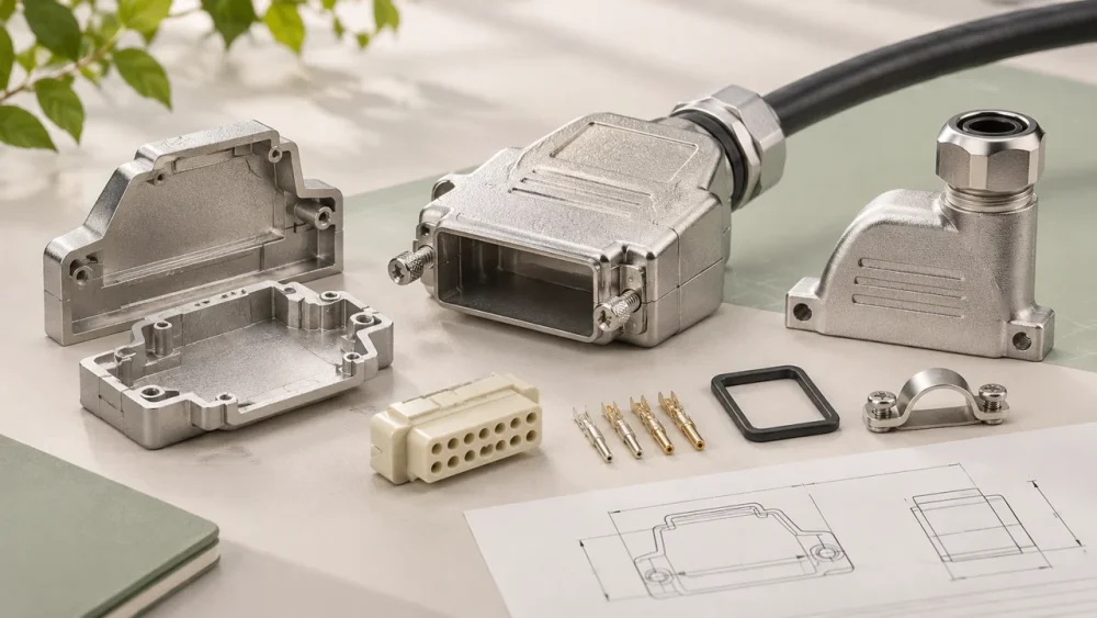
Zinc die cast connector shells provide a mechanical enclosure around electrical contacts and inserts. Gairun can review a cable connector housing or metal connector backshell with the mating interface, cable entry and finish requirements defined. Contacts, insulators and cable termination should be identified separately from the cast shell.
Connector OEMs need to specify the shell's role in retention, shielding and strain relief. A metal body does not establish the electrical rating of the finished connector. The quotation and approval plan should distinguish component dimensions from complete connector performance.
Specify the connector boundary in the purchase description
State whether you need shell halves, a complete metal body, a coupling element or a backshell.
Identify any inserts, seals or cable clamps requested with it. A supplier can then assess the metalwork without assuming responsibility for an undefined electrical assembly.
For existing connector families, supply the interface drawing and revision rather than a commercial series name alone.
Confirm which contact surfaces must remain conductive and which dimensions are measured after finishing. Those details affect processing and acceptance more than the appearance of the unassembled shell.
Define the shell boundary
Identify which components are supplied with the shell and which are provided by another organization.
A quotation for a casting does not automatically include contact insertion, cable termination or final electrical testing. The scope should make that boundary clear.
Provide the insert envelope, locating features and required clearances.
The metal should support the intended structure without placing unintended load on electrical contacts or insulation. Assembly access must allow the insert to be installed in the correct orientation.
For a panel-mounted part, include the panel opening, thickness and fixing arrangement.
The shell's external dimensions may be less important than the relationship between the mating interface and the mounting face. Use the actual installation geometry as the reference.

Mating and locking geometry
Threads, bayonet features and latches need to be reviewed against the mating component.
A nominal connector size does not define all of these features. Share the controlled interface drawing or standard that governs interchangeability.
Coating and trimming can affect the final engagement.
Define whether dimensions apply after finishing and identify surfaces where burrs or residual material would obstruct operation. A fit trial should use representative finished components.
Locking behavior also depends on springs, seals or other parts outside the casting.
Specify the assembled engagement and release requirements where relevant. A shell that meets its drawing may still need a system trial to establish satisfactory connection behavior.
Cable entry and strain relief
The cable entry must accommodate the selected cable diameter, bending requirements and retention method.
A gland, clamp or separate boot may transfer loads differently. Define the actual assembly rather than assuming any cable can be used with the same opening.
Strain relief should prevent ordinary cable forces from being carried by vulnerable terminations.
The required pull and bend performance belongs to the complete connector and cable assembly. The metal component's role should be identified within that test.
Check internal edges near the cable and insulation.
Sharp features or uncontrolled burrs can damage materials during assembly or repeated movement. Specify edge treatment and inspection in the locations that matter.
Conductive contacts and coating
Where the shell contributes to shielding or grounding, continuity must be maintained through the intended contact path.
Coatings, joints and fastening conditions can affect that path. Identify contact surfaces that need a particular treatment or controlled masking.
Do not treat the presence of a metal shell as proof of electromagnetic performance.
Openings, seams, cable shield termination and the complete device design influence the result. The responsible electrical team should define the required system evaluation.
Corrosion requirements should be considered alongside electrical function.
A finish selected for appearance alone may not suit the contact interface. The surface finishing page explains how to separate cosmetic, dimensional and functional requirements.
Assembly and environmental verification
Check insert retention, locking, panel fit and cable entry using the intended mating parts.
Record the revision and finish of each component. Interchangeability should be established through the relevant drawing and trial, not inferred from a visually similar connector.
Environmental ratings depend on the complete assembly, including seals and cable interfaces.
A casting alone cannot be assigned a universal ingress-protection rating. State the intended exposure and the required assembled test.
If the shell changes after qualification, assess whether the change affects sealing, electrical continuity or mechanical engagement.
The quality page provides a framework for connecting the change with the appropriate checks.
Send connector interface files
Provide the shell model, dimensioned drawing, mating interface, insert details and cable-entry requirements.
Add finish, inspection, quantities and any assembly scope. Identify the requirements controlled by an external connector standard or customer specification.
Request a connector shell review with mating geometry and the required supplied condition.
Agree the metal-part checks and the separate complete-connector tests before sample approval.