Custom Zinc Microphone Bodies for Audio Assemblies
Review microphone bodies, cast end caps and housing components with Gairun. Compare construction routes, internal interfaces and the supplied metal parts.
Discuss your requirements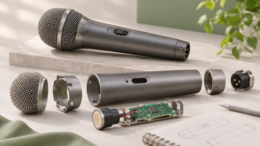
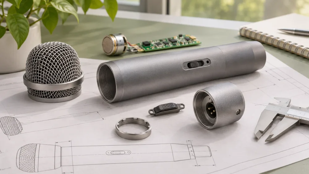
A custom microphone body order may cover the main housing, a cast end cap or selected control and connector components. Gairun can review these metal parts against your capsule, PCB and assembly envelope. State which pieces are required rather than treating every microphone housing tube as a die-cast component.
Audio OEMs should compare casting with other appropriate body constructions when the geometry is long or simple. The chosen route needs to support internal mounting, finish and access. Acoustic performance remains a property of the complete microphone, including isolation and grille arrangements.
Define the housing parts before comparing routes
A tube-shaped exterior may be assembled from parts made by different processes.
Identify the body, end cap, grille connection and switch features separately. This allows the quotation to address the cast elements without assuming the same process suits the entire shell.
If the design replaces an existing body, include connector location and service access as fixed interfaces.
Ask for sample inspection of those features before judging the cosmetic finish. A visually close replacement that changes capsule support can affect final assembly and handling noise.
Define the microphone body assembly
Locate the capsule, circuit board, connector and any internal supports.
Identify the clearances needed for wiring and assembly tools. The body should allow installation without applying uncontrolled force to sensitive elements.
The chosen construction needs a practical closure and service arrangement.
A threaded end cap, screw-fastened cover and permanently joined body create different requirements. Include the intended repair or replacement access where it affects the design.
Show the relationship between the metal body and grille or acoustic openings.
The body should not unintentionally obstruct the intended sound path. Acoustic geometry must be reviewed by the product engineering team rather than inferred from a similar-looking housing.

Capsule support and internal access
Mechanical isolation can reduce the transmission of handling or structural vibration, but its performance depends on the complete arrangement.
The cast body must locate the isolating elements correctly and avoid unwanted contact that bypasses them.
Provide the support and retention details with the body drawing.
A mounting feature that fits a component may still be too rigid, too loose or poorly positioned for the intended acoustic function. The assembly trial should evaluate the actual support system.
Access matters during both assembly and service.
Components should be installable in the required order, and wires should not be trapped by closing parts. Review the process with representative internal parts before freezing the housing geometry.
Connector and switch interfaces
Connector openings need sufficient clearance and accurate location relative to the internal assembly.
The connector should be mechanically supported as intended rather than relying on solder joints to resist cable forces. Include any panel nuts, screws or retaining parts.
Switches and controls require a defined movement envelope.
Coating buildup, burrs or misalignment can interfere with operation. Finished-condition dimensions should be specified where the surface treatment affects the fit.
Threads and mounting interfaces may require secondary machining.
The machining page explains how fixturing and datums connect those features with the casting. The route should be confirmed for the actual geometry and inspection requirements.
Handling noise and surface contact
A microphone is often held or moved during operation.
The grip shape, surface texture and mechanical coupling can influence the user experience. A comfortable exterior should be considered alongside the product team's evaluation of handling noise.
The finish may encounter perspiration, cleaning and repeated contact with stands or clips.
Define the expected exposure and visible-surface standard. A metallic color name does not establish resistance to those conditions.
Where the body interfaces with a clip or mount, check the actual contact geometry.
Excessive clamping can damage a finish or distort a local section. The sample should be evaluated with the intended support accessories.
Finish and acoustic validation
Approve the finished body for appearance, dimensions and assembly fit.
Then evaluate the microphone's acoustic and electrical behavior in the complete configuration. These are related approval stages, but a component inspection cannot replace the final product test.
Changes to openings, internal supports or mass distribution may affect the system.
A decorative revision can therefore require more than a visual approval if it changes functional geometry. Keep the tested configuration connected to the released body drawing.
The quality page explains how to separate inspection reports from product-level test evidence.
Any acoustic performance claim should come from the microphone manufacturer's validated results, not from the fact that the enclosure is die cast.
Prepare the microphone body package
Provide the body model, internal component references, connector and control details, finish and expected quantities.
Include the assembly sequence and any required dimensional or appearance records. Identify whether grilles, mounts or other components are included in the requested scope.
Send the microphone body assembly with the required metal parts and internal envelope.
Use the review to establish a suitable construction and the mechanical sample checks before device-level audio evaluation.