
Zinc die casting design begins with a decision about the part's duty and production route. A geometry that fills a die is not necessarily a geometry that performs reliably in an assembly. Material selection, wall arrangement, extraction, tolerances and operating conditions need to be considered together before tooling is released.
This guide provides a framework for that review. It does not assign a universal minimum wall, tolerance or load rating to every zinc component. Those values depend on the selected alloy, geometry, tooling, process and acceptance method, and they should be confirmed for the actual drawing.
Decide whether casting fits the project
Start by defining the function of the part.
Does it locate components, transmit motion, carry sustained load, protect electronics or provide a decorative surface? Several functions can exist in one casting, but each creates its own requirements and possible failure modes.
Then consider the expected demand and design stability.
A reusable die can be attractive for repeat production of a defined geometry. If the design is likely to change substantially, the tooling decision should account for the cost and timing of those revisions.
Compare complete production routes. A cast part with extensive secondary machining may be less attractive than a simpler casting or a different process. Conversely, a casting that integrates several useful features may reduce assembly and fabrication steps. The relevant comparison is the finished, accepted component.
Some products should remain candidates for sheet forming, machining, engineering polymers or another casting material.
A thin bookmark, a large lightweight enclosure and a highly loaded gear present different tradeoffs. The material choice should follow the requirements rather than a preference for one process across the whole product range.
Zamak 3 and Zamak 5 in context
Zamak 3 and Zamak 5 are established zinc die casting alloy designations.
They differ in composition and properties, including the effect of copper content. The choice should use reliable alloy data and the conditions relevant to the proposed part rather than treating the names as interchangeable purchasing shorthand.
Mechanical properties need their test context.
Values from a standardized specimen do not directly predict the behavior of every casting shape, local section or service condition. Casting quality, geometry and stress concentration influence how the finished part performs.
The International Zinc Association's property resources provide a starting point for alloy-specific review.
Use such data to compare candidates, then confirm the supplied material and validation requirements with the manufacturer. Industry data is not evidence of a particular factory's alloy inventory or process capability.
Do not describe one alloy as universally superior.
A property that helps one application may have limited value in another. A decorative component may prioritize finish and formability, while a functional part may need a more detailed assessment of strength, stability, temperature and wear.
Material control should connect the specified designation with the actual supply.
Agree whether material certificates, composition testing or batch traceability are required. A generic statement that a product is zinc alloy does not establish the composition needed for a controlled engineering program.
Walls, ribs and transitions
Wall arrangement influences filling, cooling and local strength.
Abrupt changes between thin and heavy regions can make production more difficult and create local behavior that differs from the rest of the part. Review transitions as part of the complete geometry rather than applying an isolated thickness rule.
Ribs can support a surface or connect features without making the entire wall solid and heavy.
Their orientation should follow the required stiffness and the tool's practical constraints. A rib that obstructs extraction or creates an inaccessible recess may introduce a new problem while solving another.
Bosses should connect to surrounding material through considered geometry.
A fastening feature can be loaded during assembly even when the product experiences little load in service. Review thread engagement, tightening method and the support around the boss together.
Internal corners and sudden section changes can concentrate stress.
Appropriate radii and transitions can improve the geometry, but their effect on mating components and appearance must also be considered. A radius should not be added blindly where it prevents a component from seating.
The IZA design rules discuss production concerns such as local thermal concentrations and moving cores.
These principles help frame a design review, while the actual dimensions remain a project-specific decision.
Draft, cores and parting lines
Draft helps release a formed surface from the tool.
The practical requirement depends on feature depth, orientation, surface condition and tool arrangement. Internal and external surfaces can behave differently during extraction, so one nominal angle is not a complete design strategy.
Choose a likely tool opening direction early.
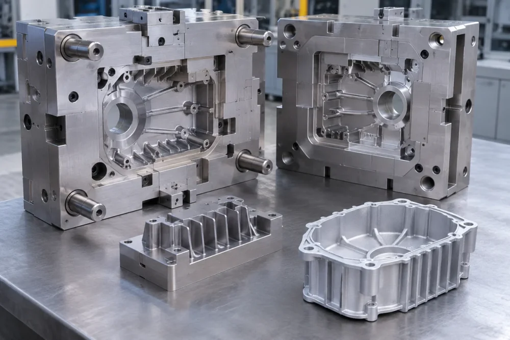
It affects which features can be formed directly and which may create undercuts. An undercut may require a moving core, a separate component or a later operation. Consider whether its function can be preserved with a simpler geometry.
The parting line should be reviewed against visible faces, sealing areas and dimensional references.
A line across a decorative surface may be acceptable after agreed finishing, while a line across a critical interface may require a different approach. State the functional and cosmetic priorities before tool design.
Core features also need support and access.
Deep, narrow openings may be difficult to form or inspect. If a passage must be machined instead, identify the resulting datum and access requirements. A hole shown in a model does not explain how it will be produced.
Gate and ejector locations are part of the manufacturing definition.
They can leave marks or require trimming. The buyer should identify prohibited locations, but the manufacturing review must still ensure that the part can fill and release reliably.
Datums, tolerances and machining allowances
A datum is a reference used to locate or orient other features.
Select datums that reflect how the part functions in its assembly. If mounting holes locate a sensor relative to an opening, the drawing should control that relationship directly rather than relying only on unrelated overall dimensions.
Tolerances should express the variation the assembly can accept.
Applying a tight tolerance everywhere can increase tool, machining and inspection demands without improving the product. Identify critical characteristics and give other dimensions a justified, practical requirement.
Consider the tolerance stack between mating components.
Two parts can each meet their individual dimensions yet fail to assemble if the relationship has not been analyzed. Include coatings, inserts, gaskets and soft components where they influence the fit.
State the measurement condition. A finished dimension may differ from an as-cast one after polishing or coating. If a surface is machined, the drawing should show the required final geometry and the production review should establish adequate allowance and fixturing.
Machining is not a universal cure for an unsuitable casting.
It adds handling and can expose porosity beneath the surface. For a sealing face or pressure-related feature, that consequence needs evaluation. Confirm the machining and inspection route instead of assuming all features can be corrected later.
Thermal, wear and environmental limits
Operating temperature affects more than immediate strength.
Sustained load and temperature can influence time-dependent deformation, so the duration and load condition matter. A short room-temperature check cannot establish long-term behavior in a warm, continuously loaded assembly.
Wear depends on the contact pair, surface condition, lubrication, movement and load.
A zinc gear or pivot should be assessed with its actual mating component. The fact that the part is small does not remove the need to evaluate repeated motion or shock loading.
Thermal design should use the complete heat path.
Alloy conductivity is one input, alongside contact resistance, surface area, airflow and allowable temperatures. Zinc may suit an integrated thermal structure, while aluminum or another solution may better meet a weight or heat-dissipation requirement.
Environmental exposure can include humidity, salts, cleaners, cosmetics and contact with other metals.
The substrate and coating system should be assessed together. A decorative finish that performs adequately indoors may need a different qualification basis in a wet or chemically exposed environment.
For fluid-containing parts, add pressure, media compatibility, leakage and long-term loading to the assessment.
A pressure rating must come from the component design and relevant validation. It cannot be borrowed from another zinc casting used in a different system.
Plan validation before freezing the design
Define the evidence needed to show that the component works.
Dimensional inspection establishes drawing characteristics; assembly testing evaluates interaction; environmental testing evaluates specified exposure. These forms of evidence complement each other but are not substitutes.
A prototype can answer useful questions without representing the final casting process.
A machined or printed model may confirm space and handling while differing in material, surface and internal structure. State which conclusions can legitimately be drawn from each prototype stage.
The production sample should represent the intended material, finish and assembly configuration where those affect the result.
Record the revision and the test conditions. If the design changes, identify which conclusions remain valid and which checks need repeating.
Use the quality planning page to connect requirements with methods and reports.
The manufacturing overview explains how tooling, forming and secondary operations fit together. Early agreement on these steps reduces the chance of discovering a qualification gap after the tool is complete.
Continue with feature-specific dimensional planning
For detailed tolerance allocation, datum selection and measurement agreement, use the zinc casting tolerance guide. This design guide establishes material and geometry suitability; the dedicated dimensional guide turns the assembly requirement into a measurable final drawing.

Example: choosing a route for a small instrument cover
Suppose a hypothetical cover needs a shaped exterior, mounting bosses and an internal space for electronics.
A casting route may combine these features, but the design team should compare it with alternatives using the actual volume, environment and assembly. This example is a design exercise, not a statement of Gairun production capability.
Identify the features that justify the process.
If the enclosure is mostly a simple thin sheet, a fabricated route may be worth comparing. If shaped bosses and repeated three-dimensional detail are central, evaluate how a die could form them and where secondary work would remain.
Keep material selection separate from the visual preference for metal.
Zamak 3 and Zamak 5 are candidates to evaluate against the specified duty and sourcing route, not interchangeable names. Record the chosen alloy and its applicable material requirements before releasing the tool design.
Design review checklist
Before requesting tooling, assemble a clear engineering package:
- A controlled model and drawing with consistent revision identifiers.
- The part's function, operating conditions and mating components.
- The required material designation or the permitted material alternatives.
- Critical datums, dimensions and finished-surface requirements.
- Acceptable parting, gate, ejector and finishing locations.
- Secondary-operation, assembly and packaging requirements.
- Sample, inspection and product-validation acceptance criteria.
Review open decisions with the people responsible for design, purchasing, quality and assembly. An unresolved interface should remain visible as a question until it is agreed, rather than being hidden in a broad tolerance or generic material note.
Send Gairun your design package for a manufacturing suitability discussion. The most useful review connects geometry with material behavior, the proposed production route and the evidence required to approve the finished component.

