
Zinc die casting tolerances should be assigned to the features that determine assembly and function. There is no single accuracy figure that responsibly describes every casting, size and production route. The appropriate requirement depends on the geometry, tool arrangement, material condition, secondary operations and measurement method.
This guide explains how to turn an assembly need into a measurable drawing. It connects feature requirements with the manufacturing and inspection decisions needed to evaluate them. The actual supplier route must be reviewed against the released requirements and supported by suitable sample or production evidence.
Begin with the assembly requirement
Identify what must happen when the part is used.
A cover may need to close against a gasket, a gear may need to align with its shaft and a cabinet pull may need to match prepared mounting holes. These functions create different dimensional relationships.
Ask what variation the assembly can accept before it fails to fit or perform.
That question is more useful than selecting a tight tolerance because it appears on another supplier's website. A requirement should have a reason connected to the product.
Distinguish critical characteristics from dimensions that mainly describe the outline.
Some external dimensions can accept more variation without affecting use. Applying the same narrow limit everywhere can increase tooling, machining and inspection demands without improving the component.
The product engineer should also identify the consequence of nonconformity.
A cosmetic gap and a safety-related alignment issue require different attention. The inspection and qualification plan should follow that significance rather than treat all drawing dimensions as equally important.
Understand tool-related variation
The way a feature is formed influences its achievable control.
Features produced within one tool section can have a different relationship from those located across a parting line or by moving elements. The drawing should be reviewed with an understanding of the proposed tooling arrangement.
Draft affects the size of a feature at different positions along its depth.
If a dimension is measured at a specific plane, identify that plane. Otherwise, two measurements can differ while both operators believe they are following the same drawing.
Parting-line effects, trimming and ejector contact can matter on selected surfaces.
Their acceptability depends on the function of the region. A residual feature acceptable on a hidden face may be unacceptable on a sealing or locating surface.
The NADCA design sourcebook is a useful reference for understanding why die casting geometry and tolerancing need to be considered together.
Published guidance is not a factory-specific guarantee, and the applicable edition and table conditions should be checked before adopting numerical values.
Tool design and process control can improve particular characteristics, but the cost and evidence requirements should be understood.
A tighter requirement may need additional trials, selective machining or a different design. It should not be accepted merely by repeating the word precision in the quotation.
Choose functional datums
A datum establishes a reference for locating or orienting other features.
The reference should reflect how the part sits and works in the assembly. A convenient exterior face is not always the correct reference for a sensor, bore or mounting pattern.
Consider the sequence in which the component is constrained.
A primary seating surface may establish orientation, while additional features locate the part laterally or rotationally. The drawing should communicate those relationships clearly enough for production and inspection to reproduce them.
Avoid creating a datum system that cannot be accessed or measured reliably.
If the reference surface is rough, interrupted or altered by finishing, discuss how it will be represented during inspection. A theoretically correct reference still needs a practical measurement approach.
For flexible or easily distorted geometry, specify the relevant measurement condition.
A part may have a different shape when free, lightly supported or clamped. The condition should reflect the requirement rather than allow arbitrary fixturing to change the result.
Allocate tolerances across the assembly
Several parts often contribute to one functional gap or alignment.
The casting, insert, fastener, coating and mating component may all introduce variation. Analyze the relationship as a system instead of assuming each individually acceptable part will always assemble successfully.
For example, a cap fit depends on the shell, liner and mating closure.
Tightening only the shell dimension may not resolve variation elsewhere. The allocation should address the contributors that actually control retention and seating.
Worst-case and statistical approaches answer different questions and require appropriate assumptions.
The engineering team should choose a method suitable for the product and available process information. Do not assume a statistical distribution or independence between dimensions without evidence.
Consider assembly adjustment and compliance where they are part of the design.
A slot, gasket or flexible element may accommodate variation, but it has limits. Those limits should be defined and verified rather than treated as unlimited tolerance relief.
The OEM development page discusses how to coordinate these interfaces across suppliers.
One organization should own the complete relationship so incompatible assumptions do not persist in separate component drawings.

Specify the finished condition
Polishing, machining and coating can change dimensions and surfaces.
State whether a requirement applies to the raw casting, an intermediate part or the final supplied component. The buyer normally needs the finished product to meet its assembly requirements.
Polishing may soften edges or change local form.
Coating can add thickness and alter close clearances. If a region must remain controlled or untreated, show that requirement explicitly rather than relying on an informal instruction during production.
Machined features need a datum strategy and adequate allowance.
The operation should preserve the relationship between the finished feature and the rest of the casting. A highly accurate bore is of limited value if it is accurately placed in the wrong position.
Temperature and conditioning can also matter to measurement and stability.
Where these effects are relevant, define the inspection conditions and any required conditioning through the responsible engineer. Avoid borrowing a universal aging or temperature rule from an unrelated alloy or process.
See secondary machining and surface finishing for the production questions associated with these final-condition requirements.
Match measurement to the requirement
Select a method capable of resolving the characteristic at the required level.
A simple size measurement, a profile relationship and a functional fit can require different equipment or fixtures. Instrument resolution alone does not establish measurement suitability.
The method should follow the drawing's datums and feature definition.
If production and inspection use different references, they may disagree about the same part. Resolve that interpretation before samples are submitted for approval.
Measurement uncertainty and repeatability matter when results approach an acceptance boundary.
The parties should understand how the method supports a reliable decision. A result displayed to many decimal places does not automatically provide meaningful accuracy.
Functional gauges can be useful where they represent the assembly requirement.
They should have a controlled definition and appropriate maintenance or verification. A successful gauge result should not be claimed to prove unrelated drawing characteristics.
Document the inspection method for critical features sufficiently to reproduce it.
Photographs of the setup, fixture references or a written method can help when several sites perform the check. The aim is consistent interpretation, not unnecessary paperwork for every simple dimension.
Use samples and capability evidence
A first-article report shows results for the inspected sample under defined conditions.
It can reveal a tool or process issue and support initial approval. It does not by itself establish how a process behaves across future production.
Where a capability study is required, agree the sampling, process condition and statistical method.
The study should represent the intended route and the relevant source of variation. Do not calculate a reassuring index from a few selected parts and treat it as a universal production guarantee.
If results do not meet the requirement, examine the cause before changing the drawing.
The issue may involve geometry, tooling, fixturing, measurement or an unnecessarily restrictive specification. A drawing change needs engineering approval based on function, not simply a desire to make the report pass.
Changes after qualification can affect the evidence.
Tool repair, process transfer, material substitution or a new coating may require selected checks or renewed studies. The quality page explains how to connect the approved configuration with its inspection records.
Example: calculate a simple clearance range
Consider a hypothetical slot and an inserted tab. The dimensions below illustrate arithmetic only; they are not recommended casting tolerances or Gairun capability values. Assume aligned features and ignore position, form, coating and temperature effects for this simplified example.
| Feature | Illustrative dimension | Resulting size range |
|---|---|---|
| Slot width | 10.00 ± 0.10 mm | 9.90 to 10.10 mm |
| Tab width | 9.70 ± 0.05 mm | 9.65 to 9.75 mm |
The smallest size clearance is 9.90 − 9.75 = 0.15 mm. The largest is 10.10 − 9.65 = 0.45 mm. If the assembly needs a narrower clearance range, the designer must reconsider the dimensions, tolerances or construction.
A positive size clearance alone does not guarantee assembly. Position, alignment, surface form and final coatings can change the result. The drawing and inspection plan must include those relevant effects before this calculation is used for acceptance.
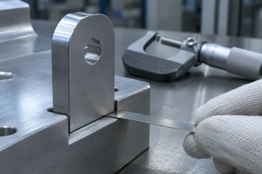
Release a measurable drawing
Before release, review the model and drawing together.
Confirm units, revision, material, datums, critical characteristics and final-condition requirements. Resolve contradictions rather than relying on an undocumented assumption about which file takes precedence.
Ensure the inspection plan can address the important features.
If a characteristic cannot be measured as defined, discuss a practical alternative before production. A requirement that cannot be verified creates uncertainty for both buyer and supplier.
Keep general tolerances appropriate to the part while defining critical exceptions explicitly.
This provides a clearer manufacturing basis than applying the most demanding requirement to every surface. The final drawing should make it easy to understand what matters and how conformity will be established.
Send Gairun the controlled drawing with the assembly context and required inspection evidence.
A useful tolerance review connects product function, the proposed manufacturing route and a measurement method that can support an objective acceptance decision.

