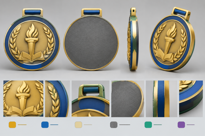
Buyers should address die casting ejector pin marks before tooling, not after finished parts arrive. The practical method is to classify every face by visual importance, mark preferred and prohibited pin zones, and approve an acceptance basis on the drawing. Final placement must also be workable for the part’s construction. Gairun’s Die Casting Tooling and Design Review can consider these instructions with the dimensions, relief, finish, attachments, and intended product format.
An ejector-pin mark is a localized casting witness associated with releasing the formed part. It is different from a parting-line witness, which follows the meeting area of tool sections. Both can affect appearance, but this guide focuses on agreeing the location and acceptance of localized ejection witnesses.
How to agree die casting ejector pin marks before tooling
A general request such as “no marks on the front” does not give the tooling team enough information. The front may contain a logo, a decorative border, a recessed field, and areas later concealed by another component. These areas do not necessarily have equal cosmetic importance.
Use a four-step decision method:
- Identify every viewing face. Show the front, reverse, edge, openings, and any surfaces exposed after assembly.
- Rank the faces. Classify them as primary visible, secondary visible, reverse or functional, or concealed after assembly.
- Map the zones. Mark prohibited areas, preferred pin zones, and areas where a casting witness may be acceptable.
- Approve the basis. Add acceptance notes to the revised drawing and resolve conflicts before tool release.
These classifications are buyer-defined and project-specific. They are not universal A, B, or C industry limits. The ranking should reflect normal viewing orientation, handling, branding, relief hierarchy, attachments, and assembly.
| Observable artwork or part input | Cosmetic priority | Initial pin-location preference | Practical reason | Variable that could change the choice |
|---|---|---|---|---|
| Front face with a fine recessed logo, portrait, or detailed emblem | Primary visible face | Reverse or genuinely concealed zone | A localized witness could interrupt the intended focal detail | Rear attachment, ejection needs, relief, or available supporting geometry |
| Broad raised rear area or non-display field | Reverse or secondary face | Less-visible rear field | The witness is separated from the main presentation face | Wall geometry, rear relief, attachment position, or finishing plan |
| Smooth front field surrounding a simple emblem | Primary visible presentation area | Outside the smooth field where feasible | Contrast may make a localized witness visually prominent | Overall form, intended finish, and workable ejection zones |
| Area covered by an assembled component | Concealed after assembly | Within the covered area as an initial preference | The witness would not be visible in normal assembled use | Component clearance, connection points, and whether the cover is permanent |
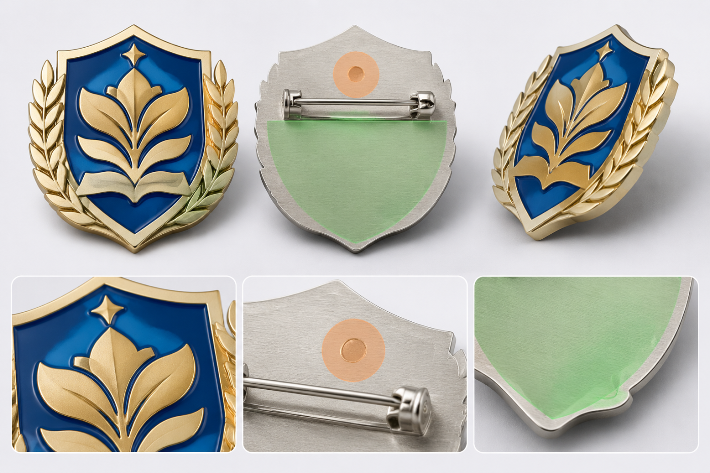
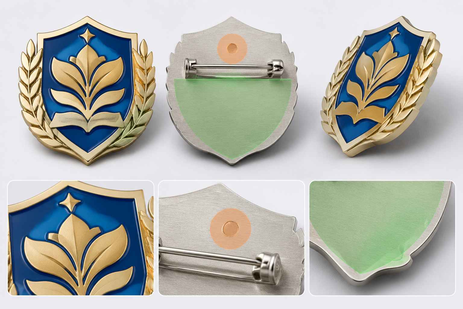
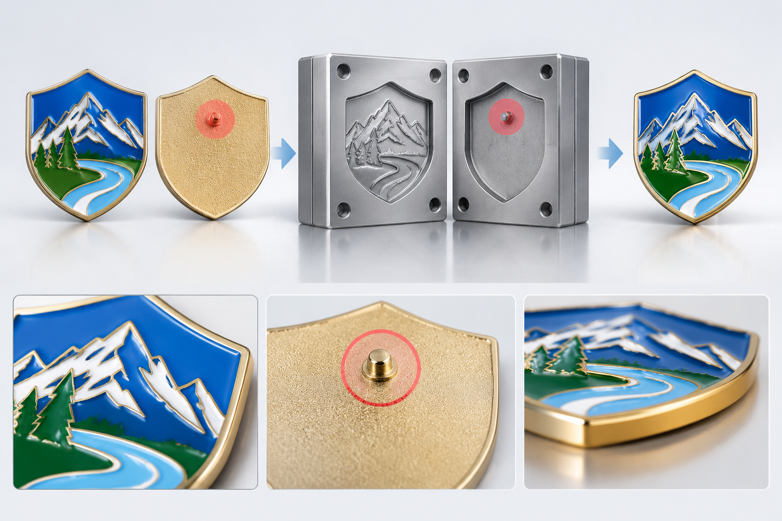
For a medal, pin, badge, or promotional component with fine front detail, the reverse may therefore be the initial preference. If the reverse also carries posts, a hanging feature, or important branding, that preference may change. A preferred zone is a design instruction, not a guarantee that every pin can be placed there. Any unresolved conflict should return to the buyer for approval rather than being silently assumed.
For related planning of the other common witness type, see Parting Lines and Ejector Marks on Zinc Castings.
Why ejection needs can override a preferred cosmetic zone
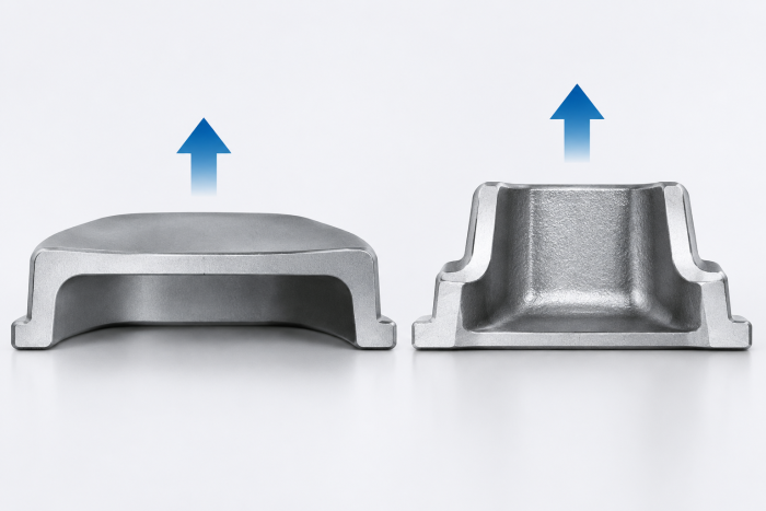
Pin placement belongs to the part’s ejection system. The tooling assessment therefore considers where controlled ejection can occur without creating an unacceptable visual consequence or compromising the intended structure. This does not create a universal rule for pin position, number, or spacing. Those decisions require the actual artwork and part construction.
Relevant inputs include the overall form, raised and recessed relief, thin-looking features, openings, rear attachments, component positions, normal orientation, and faces that remain visible after assembly. A buyer may regard a rear face as unimportant, while a rear post or attachment occupies the area initially proposed for a pin. A recessed rear logo can create another conflict if it has also been designated as protected.
The negotiation should follow a clear sequence. First, the buyer identifies the visual hierarchy and protected areas. The supplier then proposes workable zones through the tooling discussion. Both parties identify conflicts between appearance, attachments, structure, and ejection. The revised drawing records the agreed solution before tooling proceeds.
Gairun’s pre-tooling engineering review may cover dimensions, thickness, relief, metal borders, color areas, attachments, component positions, and the proposed production method. The exact checklist depends on the artwork and product structure. These inputs provide context for discussing an ejector pin location; they do not make every requested position feasible. More information about the broader forming workflow is available under Zinc Die Casting Manufacturing.
Moving a witness to a hidden face, rear field, or non-display area remains an initial preference until the tooling assessment confirms it. Buyers should not presume that a trim-tab solution is available. The approval process should also establish an escalation point. If a proposed location enters a protected logo, portrait, smooth presentation field, or designated color boundary, tooling should pause for a documented buyer decision.
Choose protected and acceptable zones from the artwork
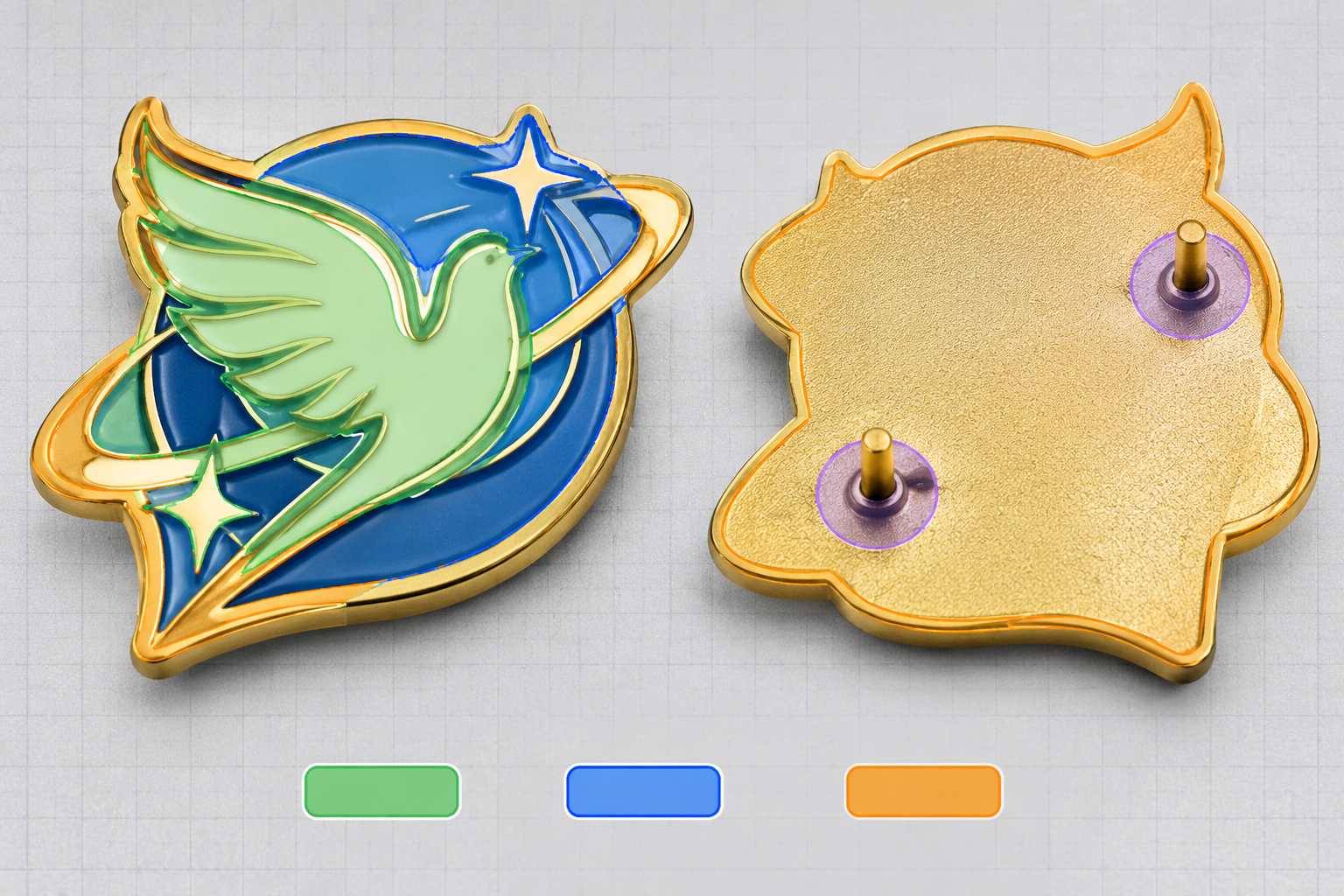
A location map is more useful than a general demand for a clean surface. Annotate both front and reverse artwork with three types of area: protected zones, acceptable witness zones, and zones concealed after final assembly. Use arrows or shaded overlays that remain legible when the drawing is shared or printed.
Protected zones normally follow the product’s visual hierarchy. They may include fine recessed text, facial or emblem details, prominent smooth fields, important borders, color boundaries, and deliberately contrasted textures. Protect these areas only when they are important to the intended presentation. Marking an entire part as protected without ranking priorities can leave no practical basis for resolving a tooling conflict.
Attachments and assembly need equal attention. A rear pin post, screw feature, hanging loop, rotating component, or connected insert can change the available area. Likewise, a face described as hidden may become visible when the product is worn, handled, rotated, or removed from its mount. Show the normal viewing orientation and attachment position instead of relying on “front” and “back” alone.
For example, a zinc-alloy lapel pin may have an irregular outline and dimensional relief, with a recessed logo on the front. The initial instruction could prohibit witnesses within that logo and prefer a rear non-display field. However, the selected attachment location and rear geometry could require a revised zone. A multi-component medal may conceal part of a face in one position but reveal it during movement, so the assembled viewing states also need to be shown.
Marked-up drawing checklist
- Front, reverse, edge, and relevant assembly-view designations
- Normal viewing and wearing orientation
- Primary, secondary, functional, and concealed faces
- Prohibited and preferred pin zones
- Finish and decoration callouts for each relevant area
- Attachment, opening, and component positions
- Exact wording for acceptable and unacceptable witnesses
Gairun can begin artwork review from vector artwork, a usable PDF, or a hand-drawn concept, but no file is automatically production-ready. Dimensions, wording, front and back instructions, attachments, and product format should accompany it. In this context, a cosmetic surface means a buyer-defined presentation requirement. It does not mean the area can never show any production witness unless that outcome has been separately assessed and specified.
Set realistic acceptance expectations for marks and finishing
Do not specify a mark-free zinc casting unless the supplier has separately confirmed an achievable and inspectable requirement for the actual design. An absolute statement can create disagreement because it does not identify the protected face, viewing context, or permitted witness zones.
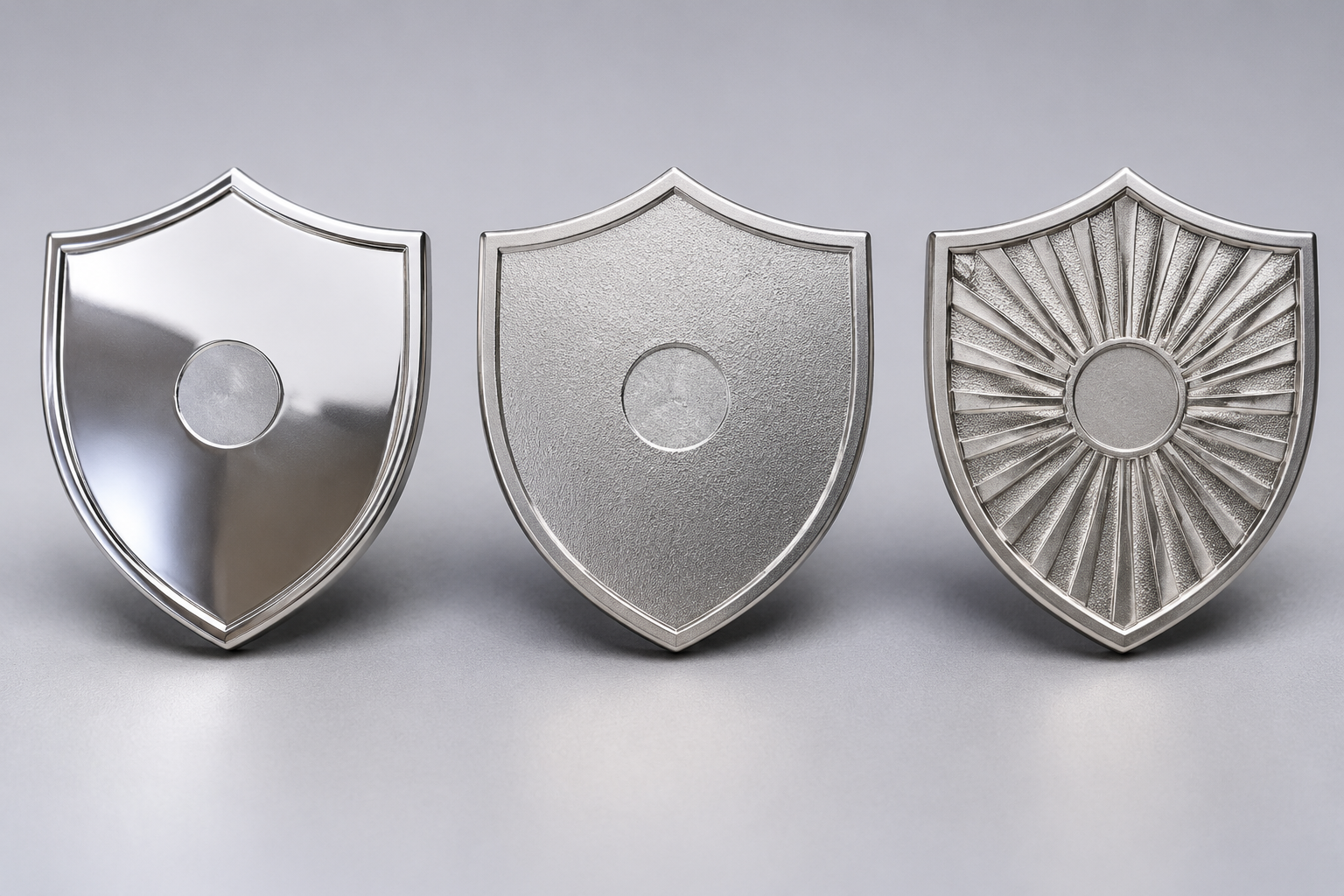
The visual effect of a localized witness can change with its location, surrounding relief, texture, reflectivity, decoration boundaries, and normal orientation. A witness in a patterned rear field may attract less attention than one in a smooth presentation area. That observation is not an automatic acceptance rule; the drawing still needs to state which area matters and what visual disruption is unacceptable.
Separate two decisions. The first is where a witness may occur. The second is how that agreed location will be judged after finishing. Keeping these decisions distinct prevents a buyer from approving a poor location merely because a later finish is expected to disguise it.
Gairun lists sandblasting and matte finishing as options for reducing shine or creating surface contrast. Suitability depends on the artwork, base metal, forming route, and width of the treated area. An exact texture or gloss should not be promised without an approved sample or specification. The Zinc Alloy Surface Finishing plan should therefore support, rather than replace, the pin-location agreement.
Gairun also describes burr inspection, polishing, flatness checks, and cleaning within its surface-preparation flow. These stages should not be converted into a universal cosmetic grade or a guarantee that every casting witness will disappear.
Use plain-language acceptance notes tied to defined areas. Suitable wording might prohibit disruption of a designated logo, border, color boundary, or smooth presentation field. It can permit a localized witness within a specifically mapped rear field, subject to the approved finished appearance. Avoid inventing defect-size, inspection-distance, lighting, roughness, or gloss limits unless the buyer supplies an applicable specification and the supplier accepts it.
Approve pin locations through the drawing, trial, and first article
The approval path should connect the original cosmetic intent to a traceable pre-production decision. A practical sequence is:
- Submit annotated front and reverse artwork with the product requirements.
- Assess the proposed pin zones with the tooling proposal and construction details.
- Resolve conflicts and approve the revised 1:1 drawing with visible-face and acceptance notes.
- Inspect the relevant appearance on the first article against the approved requirements.
- Record any accepted exception before continued production.
The approval record should include the drawing revision, front and reverse views, normal orientation, protected and acceptable zones, attachment and assembly context, finish description, agreed exceptions, and responsible approver. If the product changes appearance when moved or assembled, include the relevant viewing states.
Gairun states that after tooling and trial forming, it compares the first article with the approved 1:1 drawing for dimensions, thickness, and relief detail. This is a control point before continued production, but the project tolerances must be specified separately. Cosmetic criteria also need their own wording. Comparing a first article with a drawing does not create visual limits that were never documented.
Keep artwork approval, pin-location approval, finish or appearance approval, and any sample approval as separate control points. A single “approved” email can become ambiguous if it is unclear whether the buyer accepted only the artwork layout or also accepted a visible casting witness.
Repeat orders are not automatically covered when the artwork, visible face, relief, attachment, component position, or finish changes. Reassess the location agreement because the old drawing may no longer represent the revised part. Even a new rear attachment can occupy a previously accepted pin zone.
Turn cosmetic intent into an approval-ready pin-mark brief
The reliable objective is not an unsupported demand for invisible marks. It is a shared decision about which faces matter, where a witness may be acceptable, what construction conditions could require relocation, and how the finished result will be approved.
Send annotated front and reverse artwork, dimensions, relief and attachment details, finish intent, normal viewing orientation, protected zones, acceptable zones, and a named approval contact. A useful RFQ should also identify product type, quantity, variants, packaging, destination, and schedule. Unresolved choices can be marked for engineering discussion rather than treated as final. Buyers can use Gairun Custom Zinc Manufacturing as the starting point for submitting these requirements.
Frequently asked questions
Can ejector pin marks be completely eliminated from a zinc casting?
Complete elimination should not be assumed. Ask the supplier to assess the actual design, identify workable pin zones, and confirm an inspectable acceptance requirement before tooling. A finish should not be treated as a guarantee that every witness will disappear.
Which faces should be identified as cosmetic surfaces on a zinc die-cast part?
Identify every face visible during normal display, handling, wearing, movement, or assembly. Rank primary presentation faces separately from secondary, functional, reverse, and genuinely concealed faces. The classification should reflect the product’s actual use and visual hierarchy.
Can an ejector pin mark be placed on the back of the part?
The back is often an initial preference when the front contains important graphics or smooth presentation fields. Feasibility still depends on rear relief, attachments, component positions, overall geometry, and the ejection assessment. The confirmed location belongs on the approved drawing.
Will a matte or sandblasted finish hide an ejector pin mark?
Not necessarily. Matte or sandblasted treatments may reduce shine or create contrast, but suitability depends on the artwork, base metal, forming route, and treated-area width. Approve the location independently from the finish and use a sample or specification when an exact appearance matters.
What should a drawing show to approve ejector pin locations?
Show front and reverse views, normal orientation, visible and concealed faces, protected and acceptable zones, attachments, assembly context, relief, finish callouts, acceptance wording, revision details, and the responsible approver.
When should ejector-pin mark acceptance be checked during a custom order?
Define it before tooling, confirm the proposed location on the revised drawing, and inspect the agreed area on the first article. Record approved exceptions before continued production and reassess the decision whenever artwork, relief, attachments, visible faces, or finishing changes.