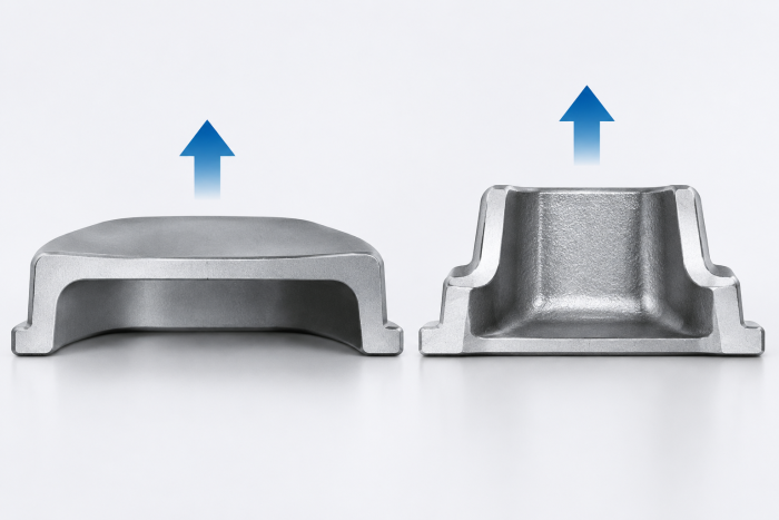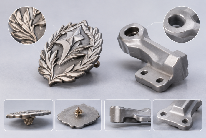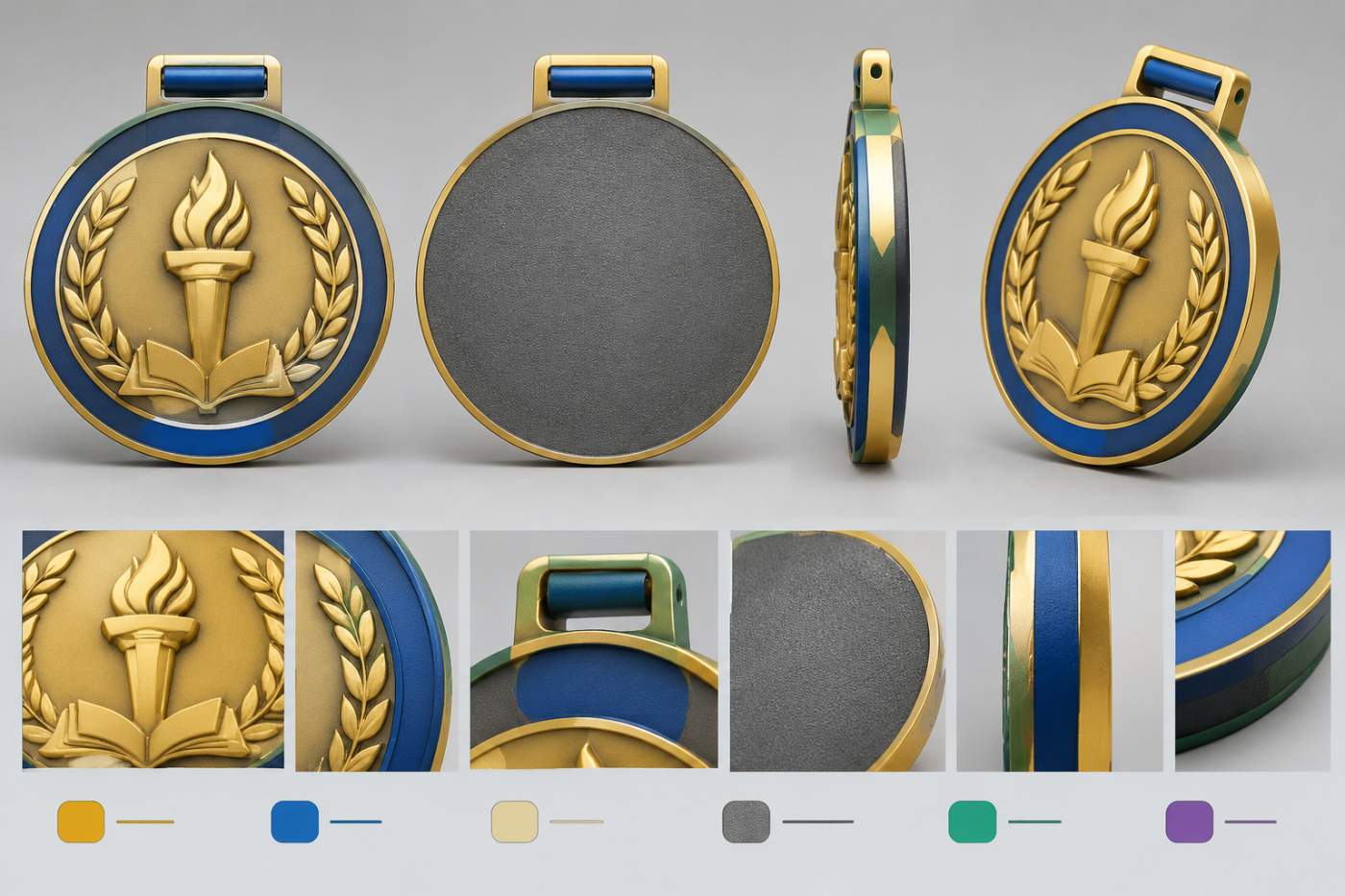
The central issue in die casting parting line cosmetic surfaces planning is not how to make every process witness disappear. It is how to protect the faces and details that matter most. Before tooling, buyers should rank each surface, mark prohibited and acceptable witness zones, and provide the casting orientation and rear-side constraints. A Die Casting Tooling and Design Review can then consider those cosmetic priorities alongside the requirements for forming and releasing the part.
This method is more reliable than requesting an entirely mark-free casting. A logo field, portrait, polished area, touch surface, or readable text may require strong protection. A rear field, sidewall, or perimeter transition may offer a less disruptive location. However, the final arrangement still depends on the part shape, relief, attachment positions, decoration plan, and proposed tooling.
Plan cosmetic surfaces before the die casting parting line is fixed
Begin with a face map rather than a general note saying “no visible marks.” Divide the design into primary display faces, touch faces, secondary faces, rear or concealed faces, and edge transitions. Within those areas, identify protected features such as logos, lettering, relief peaks, portraits, color boundaries, smooth fields, and narrow metal borders.
Next, establish the normal viewing direction. A medal viewed mainly from the front has different priorities from a badge displayed on both sides. A component that sits flush against another part may have a visually hidden surface that is still functionally critical. Rank these conditions instead of treating “front” and “back” as complete specifications.
- Show the normal viewing and handling orientation.
- Rank the display, touch, secondary, and concealed surfaces.
- Mark prohibited zones and preferred lower-visibility zones.
- Submit the map with front and back artwork, dimensions, relief direction, and attachments.
- Allow tooling engineering to identify conflicts and propose alternatives before approval.
| Observable artwork or part input | Initial cosmetic zoning recommendation | Likely tooling implication | Variable requiring confirmation |
|---|---|---|---|
| Fine recessed text or a front-facing emblem dominates the main view | Protect the front field and first consider rear or perimeter areas for witnesses | The split and release plan must avoid disrupting the protected detail where feasible | Mold-opening direction and relief geometry |
| Broad raised areas cover the front, while the back has an open field | Reserve the open back field as a preferred mark zone | Rear access may provide more flexibility, but cannot be assumed | Attachment placement, wall geometry, and ejection requirements |
| Both faces carry customer-facing graphics | Rank individual details and edge transitions instead of declaring either face fully available | Tooling may need compromises around the perimeter or lower-priority details | Part orientation, relief hierarchy, and finish intent |
| A rear surface mates with another component | Treat the interface as functional, even if users cannot see it | Cosmetic witnesses cannot interfere with the required fit or contact area | Assembly position and visible clearance |
For a design with fine recessed wording around a front emblem, the initial decision would be to protect that complete visual field. Rear or perimeter zones would receive higher acceptance priority. This is only a starting position; the relief and opening direction may require another route.
For a casting with broad raised front artwork and a relatively plain back, the back can initially be offered for marks. An attachment, assembly interface, or release requirement may reduce the usable area. The map therefore communicates priorities, not unilateral tooling instructions.
Gairun can begin artwork review from vector artwork, a usable PDF, or a hand-drawn concept. Dimensions, wording, front and back instructions, intended format, and attachment details should accompany it. No input file should be treated as automatically production-ready. Depending on the structure, Gairun’s pre-tooling review may cover thickness, relief, borders, color areas, attachments, component positions, and the proposed production method.
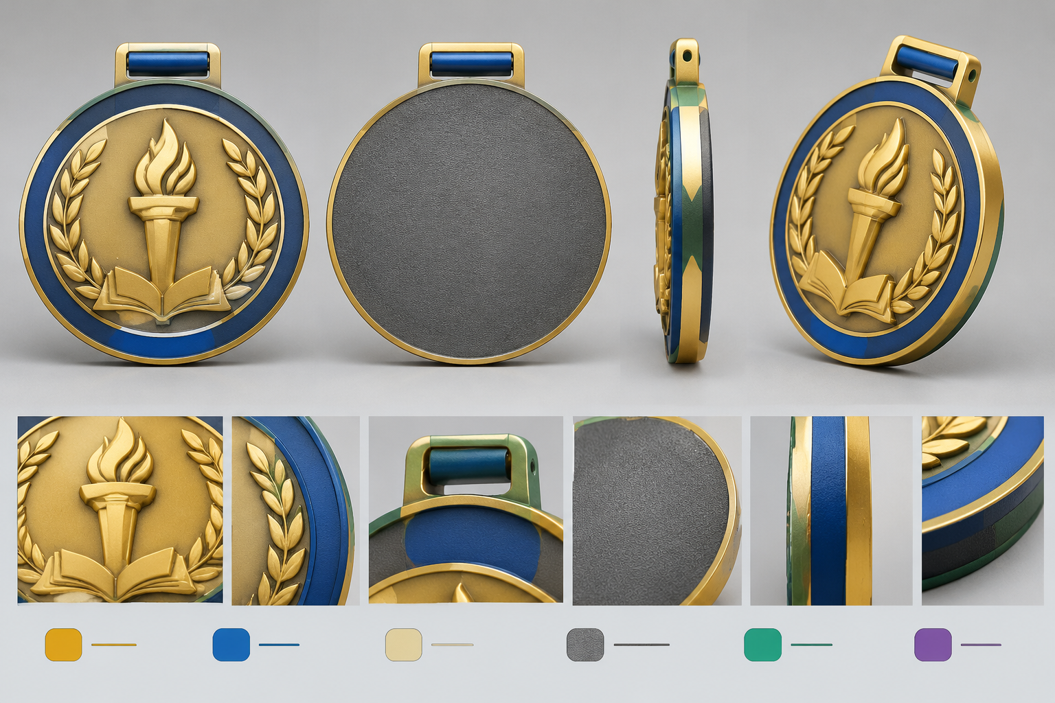
How mold opening constrains parting-line placement
A parting line is the boundary where sections of the die meet. Its possible route is connected to how the formed casting separates when the die opens. Consequently, the preferred front view alone cannot determine parting-line placement.
The outer perimeter, a sidewall, an edge, or a transition in relief may provide possible routes for discussion. A broad, uninterrupted display face offers fewer visually discreet choices. The important buyer question is not whether a line exists, but whether its proposed route crosses a critical logo, fine border, text field, portrait, or smooth presentation area.
An edge-aligned line may be less noticeable in normal viewing than a line across a polished field. A rear-facing route may protect the principal artwork. Neither result can be promised from artwork alone because extraction, geometry, and tooling construction must also be resolved. Without project engineering, there is no universal placement rule that applies to every zinc casting.
Artwork changes can sometimes improve the initial cosmetic plan. These may include changing the casting orientation, simplifying an outline transition, reorganizing the relief hierarchy, or moving secondary information between the front and back. Such changes require buyer approval because they may affect the intended appearance.
A challenge coin design, for instance, might separate a dominant subject from supporting fields through raised, recessed, layered, or sculpted forms. Identifying the dominant feature tells engineering which relief deserves the strongest visual protection. It does not establish an assumed relief depth or guarantee that every small feature will transfer unchanged.
For die-cast pins, geometry, thickness, the rear attachment area, and decoration should be defined before tooling. Those inputs help establish which surfaces may carry a less-visible split. Zinc-alloy die casting can be considered for formed outlines, irregular bodies, or more dimensional relief, but suitability still depends on the complete artwork and structure.
Gairun lists zinc-alloy die casting among its available forming routes. The route depends on material, part shape, relief structure, and decoration plan, so it should not be treated as interchangeable with stamping, photo etching, or other methods. Buyers can use the Zinc Die Casting Manufacturing overview as context, while relying on the actual design assessment for process selection.
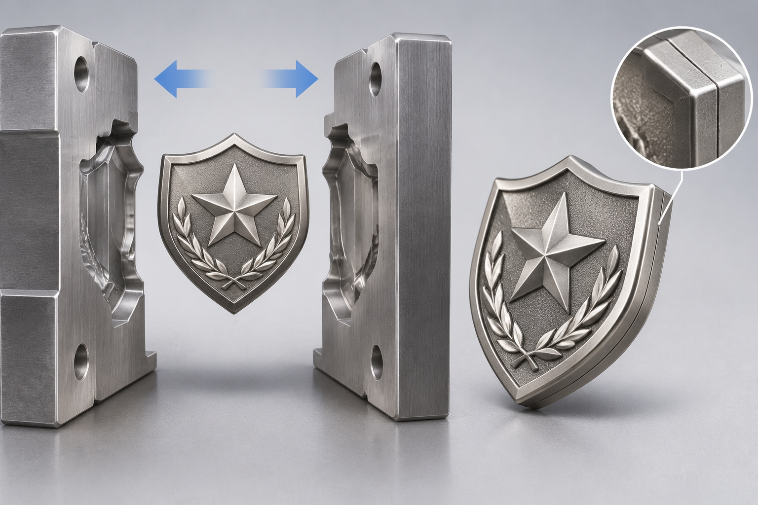
Balance gate marks and ejector pin marks with filling and release needs
Parting lines, gate marks, and ejector pin marks have different roles. The parting line follows the boundary between die sections. A gate relates to where metal enters the cavity and can leave a witness after removal. Ejector contacts assist release and may leave localized marks. Combining all three under the phrase “tooling marks” makes approval less precise.
Tell the manufacturer which areas must remain visually continuous. Typical examples include a logo field, readable wording, a smooth touch area, a color boundary, or a surface that must sit against another component. Then distinguish absolute functional restrictions from cosmetic preferences.
A blanket instruction that bans marks from the entire back can create conflicts. Rear space may already contain attachment posts, connection points, or assembly interfaces. Filling and release also need engineering consideration. A ranked map gives the tooling team room to work without weakening the buyer’s true visual priorities.
Where fine recessed detail fills the primary face, reserve that face from gate and ejector witnesses as the initial preference. Where an attachment occupies only part of the back, identify the remaining lower-visibility fields rather than declaring the complete rear surface unavailable. Engineering can then assess whether those fields offer suitable access.
Moving or connected products need an assembled-system assessment. For example, a combination or spinning medal can include component alignment, connection points, movement, and visible clearances. A surface that appears concealed in a single-part drawing may become visible during movement. A proposed witness zone must not be accepted before that relationship is understood.
Buyer checklist for mark-zone planning
- Normal part orientation and viewing direction
- Primary display face and important secondary faces
- Concealed surfaces and functional interfaces
- Attachment, post, connection, and assembly zones
- Logos, text, borders, and relief that must remain visually continuous
- Preferred and prohibited gate or ejector witness zones
- Intended finish and touch requirements
- Whether both sides are customer-facing
Gairun’s pre-tooling review may consider attachments and component positions together with relief and the proposed production method. Providing rear-side constraints at the RFQ stage makes preferred gate and ejector zones more meaningful. It also reduces the risk of protecting a cosmetically minor field while overlooking a functional interface.
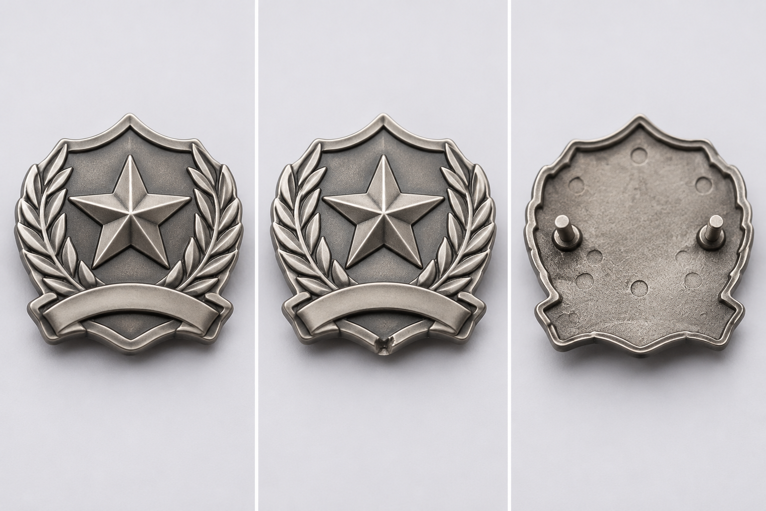
Set realistic expectations for trimming, polishing, and surface finish
Trimming and polishing should not be used as a substitute for thoughtful mark placement. Removing a gate remnant or burr is different from restoring a completely uninterrupted cosmetic surface. Local work can affect edge definition, flatness, texture, or nearby shallow relief.
A witness on a concealed edge may be easier to manage visually than one across a broad smooth field. Fine borders, shallow features, and areas intended to have a uniform sheen can be especially sensitive to local changes. This does not mean a specific mark will remain prominent; it means the finished appearance must be assessed against the approved design and finish.
Buyers should state the visual result they value most. One design may prioritize crisp relief and readable text. Another may require a smooth touch surface, controlled color separation, a uniform sheen, or deliberate contrast between fields. These criteria can lead to different acceptable witness zones.
Gairun describes its surface-preparation flow as including burr inspection, polishing, flatness checks, and cleaning before decoration. This is a process description, not a promise of a universal surface roughness, flatness tolerance, or cosmetic grade. Any measurable tolerance or appearance criterion must be stated separately for the order.
Sandblasting and matte finishing can be considered when the design calls for reduced shine or surface contrast. Suitability depends on the artwork, base metal, forming route, and width of the treated area. Exact texture or gloss requires an approved specification or sample. A matte instruction should not be interpreted as a guarantee that an inconveniently located witness will become invisible.
The finish plan and witness map should therefore be assessed together. The proposed mark location must be considered after the intended decoration is understood, not only on an undecorated drawing. Gairun’s Zinc Alloy Surface Finishing information can support the initial discussion, but the selected appearance still needs design-specific approval.
Approve the cosmetic plan in drawings, proofs, and first articles
The approval package should make cosmetic intent traceable. Include annotated front and back artwork, the normal viewing orientation, a face-priority legend, protected details, acceptable witness zones, attachment positions, relief notes, and finish instructions. If a proposed parting-line route is known, show it. Also define how a conflict or requested change will be returned for approval.
A visual proof and a formed-part approval serve different purposes. A rendering can show intended colors, artwork placement, and visible-face priorities. It does not by itself confirm dimensions, structure, the actual finish, or how process witnesses appear on a formed part.
A practical approval sequence has two cosmetic stages. First, examine the formed part before decoration for the actual parting line and gate or ejector witness locations. This stage helps reveal whether protected details and interfaces have been respected. Second, assess the agreed finished appearance after the selected decoration or surface treatment is applied. Record acceptance criteria and approved changes in the project documents.
According to Gairun’s stated process, after tooling and trial forming, the first article is compared with the approved 1:1 drawing for dimensions, thickness, and relief detail. Project tolerances must still be specified separately. Cosmetic acceptance also needs its own criteria because dimensional comparison alone does not define acceptable witness visibility.
Ask how deviations will be presented if a requested no-mark zone conflicts with tooling needs. The appropriate response may be a revised zone, orientation, relief arrangement, or other documented proposal. An undocumented relocation should not be treated as acceptable merely because the general artwork was approved.
RFQ-ready information
- Product type, quantity, dimensions, and design variants
- Vector artwork, usable PDF, or concept drawing
- Front and back instructions and normal viewing orientation
- Visible-face map with ranked mark-zone priorities
- Relief, finish, and color-treatment requirements
- Attachments, component positions, and assembly interfaces
- Packaging, destination, and required schedule
- Rule for approving cosmetic or structural changes
Gairun maintains buyer approvals as distinct control points through requirement intake, artwork and engineering review, optional sample planning, production coordination, and later order stages. Not every order requires a custom sample, but artwork approval should remain separate from formed-part cosmetic acceptance.

Make cosmetic priorities a tooling input, not a late-stage correction
The most reliable approach is to identify genuine display faces, touch areas, and protected details before tooling. Engineering can then consider parting, gate, and ejector witnesses in the least disruptive feasible zones.
For buyer-defined OEM work, production follows the buyer’s design or specification, but engineering review and buyer approval remain necessary. Submit annotated artwork, part orientation, attachment constraints, finish intent, and a ranked acceptance map. Use the same documents when evaluating the first formed article and the agreed finished appearance.
Frequently asked questions
Can a die-casting parting line be completely hidden?
It may be possible to place a parting line on a less-visible edge, sidewall, perimeter, or rear area, but complete concealment should not be assumed. The feasible route depends on mold opening, part geometry, relief, and extraction needs.
What is the difference between a parting line, a gate mark, and an ejector pin mark?
A parting line follows the boundary where die sections meet. A gate mark is the witness associated with the metal-entry location after gate removal. An ejector pin mark is localized contact evidence associated with releasing the casting.
Should the back of a zinc casting always be used for ejector pin marks?
No. The back may contain attachments, mating surfaces, customer-facing artwork, or moving-part interfaces. Rank the available rear fields and ask engineering to assess release access rather than reserving the entire back automatically.
Can polishing remove a gate mark without changing the design detail?
Removal and polishing may affect local texture, edge definition, flatness, or adjacent shallow relief. Do not assume a gate witness can be made invisible without consequence; assess its location and finished appearance against the approved criteria.
When should cosmetic mark zones be approved during a custom zinc-casting project?
Define the zones before tooling, confirm the proposed arrangement during engineering review, inspect their actual placement on the first formed article, and assess the agreed appearance again after the selected finish or decoration is applied.