
FACTORY-DIRECT OEM / ODM MANUFACTURING
Custom Metal Product Engineering Review Before Tooling
A custom metal product engineering review is a technical feasibility check completed before mold work. Gairun reviews whether a proposed design can be formed, colored, plated and assembled as intended. We manufacture custom medals, challenge coins, pins, badges, trophies, plaques, keychains and bottle openers for designers, agencies, procurement teams and other business buyers.
Our engineers assess dimensions, thickness, relief detail, metal borders, color areas, plating direction, attachments, component clearances, assembly relationships and the proposed production method. Submit your design and specifications through our request a quote page to start a project-specific review.
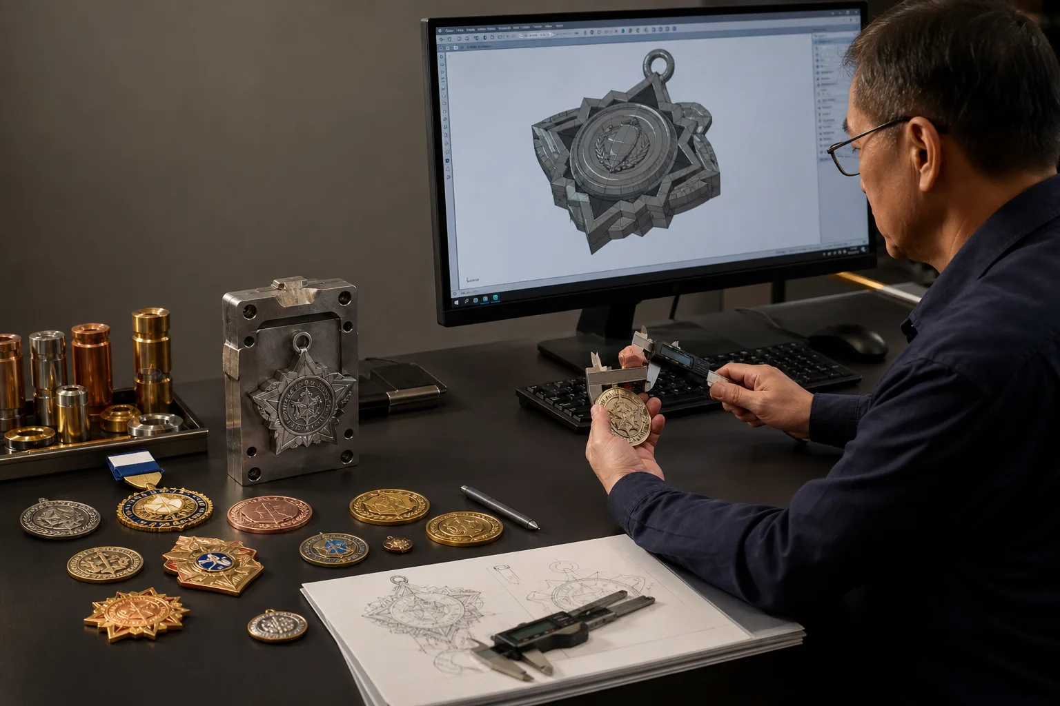
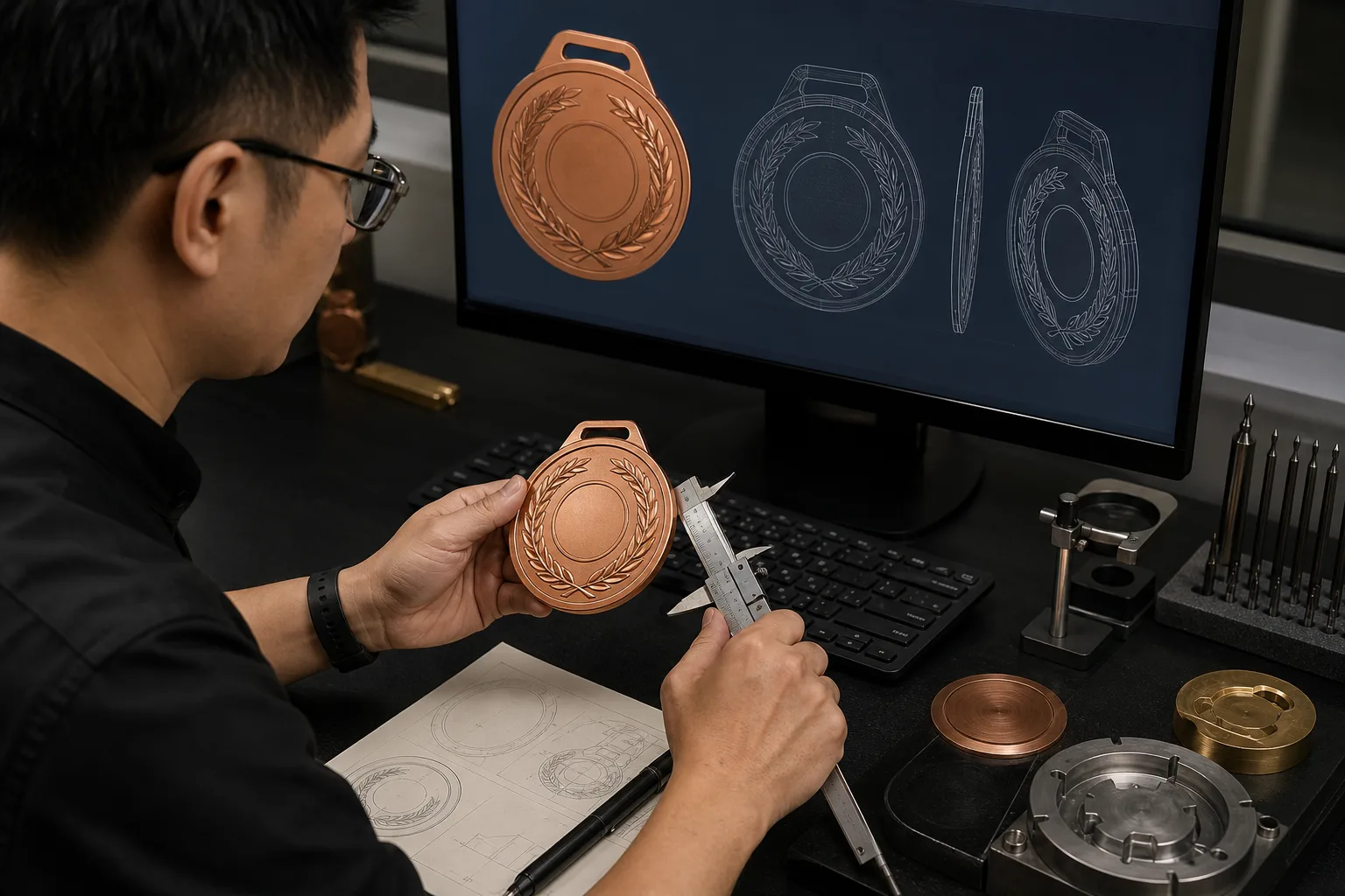
Confirm Technical Feasibility Before Mold Development
A design that looks correct on screen may still contain features that conflict with metal forming, enamel application, plating or assembly. The engineering review examines how these elements work together. It is not limited to the appearance of the artwork.
For example, a raised logo may affect the space available for surrounding enamel. A narrow opening may influence the forming route. A spinning center may need enough clearance to rotate without touching the outer component. These relationships need to be resolved before the design moves into tooling.
Our professional 2D and 3D engineering team uses AutoCAD, CorelDRAW, Adobe Illustrator, Rhino and ZBrush to support technical assessment. If your concept still needs visual development or a production-ready proof, see our artwork design and proofing service. The engineering review begins when the product structure and intended appearance are clear enough to assess.
- Forming: Can the geometry be produced by the proposed metal-forming method?
- Decoration: Can the specified color and surface treatments follow the metal structure?
- Assembly: Do attachments and separate parts have workable positions and clearances?
- Process fit: Do the material, forming route and finish support the same design?
Check Dimensions, Thickness and Component Placement
The dimensional review starts with the overall size and thickness of the product. It then examines how text, edges, openings, relief features and connection points fit within that area. Separate components are reviewed both on their own and in relation to the complete product.
Small text, narrow edges and tightly placed features require project-specific assessment. Their feasibility depends on the product size, material, forming method and planned decoration. We do not assume that a detail will reproduce simply because it is visible in a digital file.
For a multi-part design, the review also checks alignment and orientation. A rotating medal center must sit correctly inside its frame. A metal emblem on a combined award must fit the intended mounting area. A keychain connection point must be positioned so that the finished item hangs in the intended direction.
Buyers should provide the intended dimensions, thickness, front and back arrangement, and the position of any opening or connected part. Where a dimension remains undecided, we identify it as an engineering point that needs agreement before mold work.
Match Relief Geometry to the Metal-Forming Method
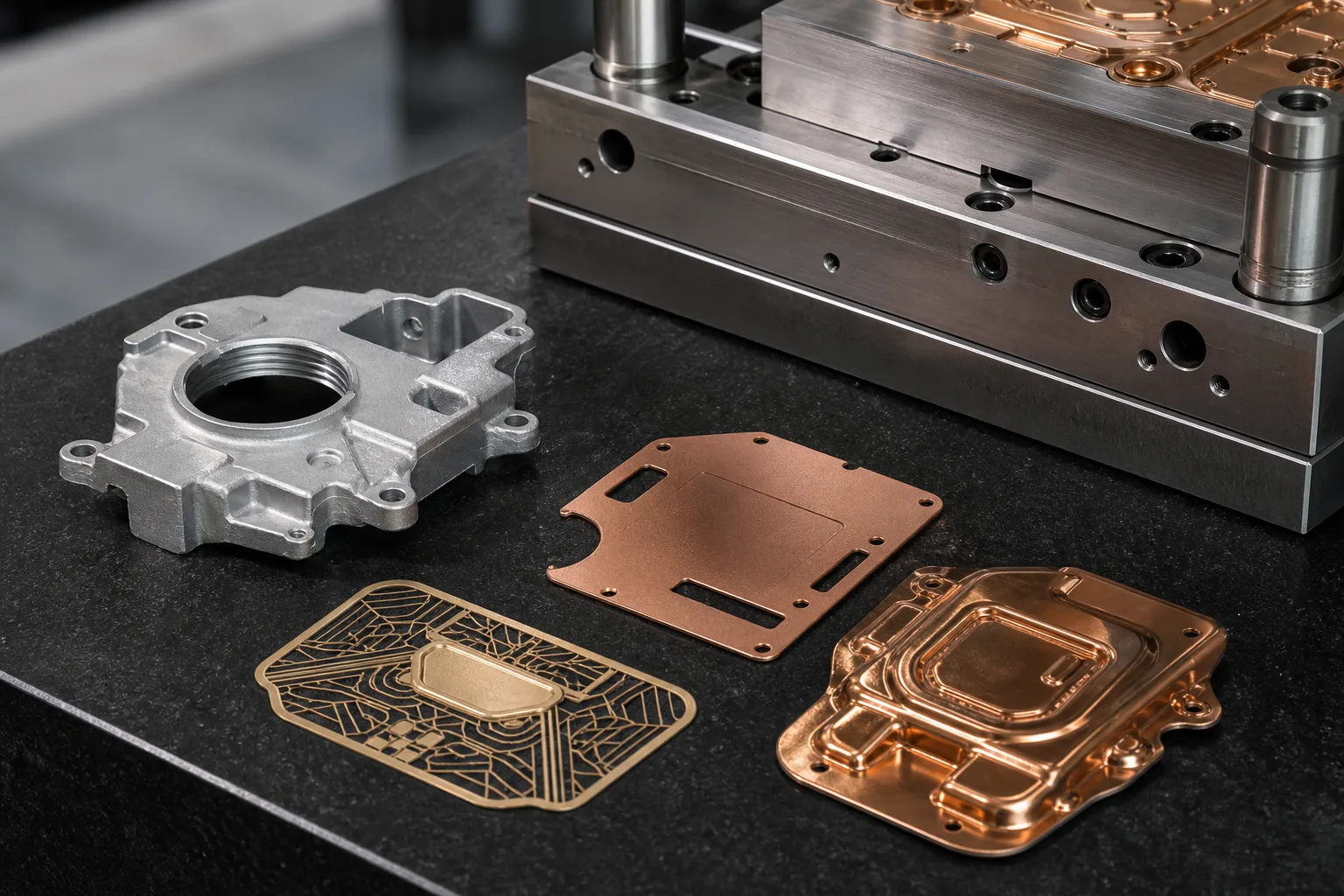
Relief changes the physical surface of a metal product. Raised areas project above the base, recessed areas sit below it, and sculpted relief uses several levels to create a more dimensional form. The depth, shape and transition between these areas influence the forming method and mold structure.
Gairun’s verified forming capabilities include zinc alloy die-casting, stamping or die-struck forming, photo etching and hydraulic high-relief forming. Our production equipment includes CNC engraving machines, 88T and 160T zinc alloy die-casting machines, and 200T and 500T precision stamping or hydraulic presses. The correct route is selected only after the geometry and product requirements have been reviewed.
| Forming route | Design question reviewed | Typical engineering focus |
|---|---|---|
| Zinc alloy die-casting | Does the design use a formed shape or dimensional structure? | Relief, openings, edges, thickness and integrated connection features |
| Stamping or die-struck forming | Can the design be formed from the selected metal and planned face structure? | Raised and recessed detail, outline, thickness and feature placement |
| Photo etching | Does the surface design call for etched detail rather than deeper formed geometry? | Line layout, recessed areas and the relationship with later decoration |
| Hydraulic high-relief forming | Does the concept require pronounced relief that needs a dedicated forming review? | Relief depth, transitions, metal flow and overall structure |
This comparison is a starting point, not a universal process rule. See our manufacturing capabilities for a wider view of tooling, forming, finishing and inspection operations.
Make Metal Borders and Color Areas Work Together
Enamel color depends on the metal structure around it. During review, we examine the borders that define each color field, the separation between adjacent colors and the available space around text or relief. The goal is to determine whether each color area can be applied without changing the intended design hierarchy.
Soft enamel and imitation hard enamel both require a workable relationship between metal lines and enclosed color areas. Fine details, very small fields or graphics without clear separation may need another treatment. Screen printing or UV printing can be considered when a detail does not translate well into separate enamel fields.
The review does not select enamel based on appearance alone. We consider the formed surface beneath it, the position of raised and recessed areas, and the way the color treatment meets nearby plating. Clear epoxy coating may also be reviewed when it is part of the requested surface design.
Broader comparisons between enamel surfaces belong in the relevant product and manufacturing guidance. Here, the decision is narrower: can the planned color method follow the specific metal structure without losing essential information?
Plan Plating Boundaries Around the Product Geometry
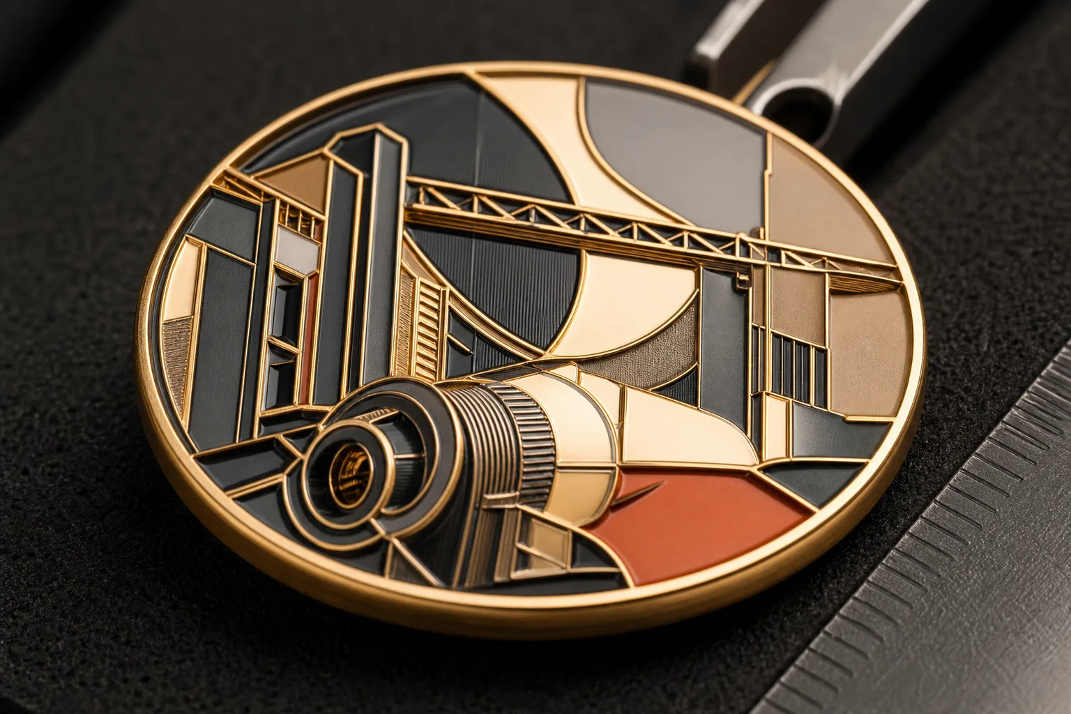
Plating direction must be assessed against relief, recessed areas and component breaks. A finish that works on a simple one-piece product may need different planning on a sculpted or multi-part design. The engineering review identifies where a plating effect begins, where it changes and how it interacts with enamel, printing or textured surfaces.
Our verified finish options include gold, silver, nickel, black nickel, antique bronze, antique silver and dual plating. Sandblasting and matte finish are also available surface effects. Their suitability depends on the product geometry and the intended visual separation.
Dual plating needs especially clear boundary planning because two metal tones must occupy defined parts of the design. Raised and recessed geometry may help create that separation, but the exact direction must be checked for each project. Antique effects, sandblasting and matte surfaces also respond to the shape and location of design features.
For a broader comparison of appearance choices, use the finish guidance available through our custom metal product range and manufacturing pages. The engineering review focuses on whether your selected effect can be applied to the proposed structure.
Review Attachments, Moving Parts and Assembly Clearances
Attachments affect both function and orientation. We review where each attachment connects, how it relates to the product body and whether the surrounding metal provides a workable structure. The assessment may cover medal ribbons, pin fasteners, magnets, keychain hardware or other project-specific components.
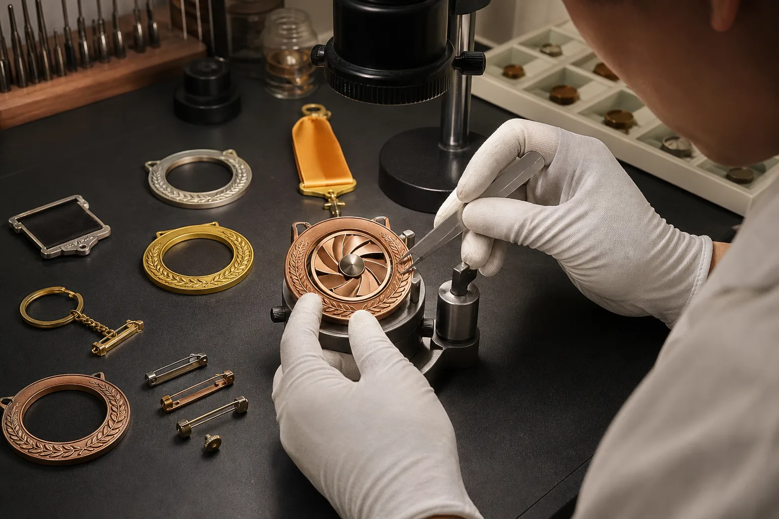
Moving and combined products require further checks. A spinning center needs clearance within its outer frame and a connection that supports the intended movement. Combined components need defined contact points, alignment and assembly order. Each part must fit without blocking nearby relief, color or finished surfaces.
The attachment type must also suit the product format. A fastener used for a lapel pin does not answer the same design problem as a medal ribbon or a magnet. We therefore assess attachments as part of the complete product rather than treating them as separate accessories.
Attachment position and orientation
Connection point geometry
Clearance between fixed or moving components
Alignment of separate parts
Interaction between assembly areas and decorated surfaces
Intended movement or final product function
Select Materials and Processes as One Production System
Material selection cannot be separated from shape, relief, decoration and assembly. Gairun works with zinc alloy, brass, iron, stainless steel and aluminum. We recommend a material and process combination after reviewing the project rather than assigning one material to every product of the same type.
A dimensional structure may direct the assessment toward a different forming route than a flatter die-struck design. Fine surface graphics may change the decoration recommendation. A multi-part product may introduce connection and clearance needs that affect both material and forming decisions.
The engineering recommendation therefore brings several choices together:
Our customization services show how engineering review connects with the wider project path, while the product pages help buyers identify the metal format that best fits their program.
01
Define the required product structure and dimensions.
02
Assess relief, openings, edges and component relationships.
03
Match the geometry to a feasible forming route.
04
Check how enamel, printing, plating or surface effects meet the formed metal.
05
Confirm attachment positions and assembly relationships.
Receive Clear Engineering Findings Before Tooling
The outcome of the review is a clear technical direction for the proposed product. It identifies feasible features, points that need adjustment, the proposed forming method, the decoration direction and relevant assembly considerations. Unresolved conflicts should be corrected before mold work begins.
For example, the findings may show that a color field needs a clearer metal boundary, that a moving component needs more clearance or that the intended relief calls for a different forming route. The purpose is to resolve production questions while changes can still be made to the design specification.
For a project-specific assessment, provide the product type, quantity, overall dimensions, intended thickness, artwork, finish, color treatment and attachment requirements. Include front, back and component views when they affect relief, plating or assembly. These details give our engineers the context needed to evaluate the whole construction rather than one isolated feature.