
FACTORY-DIRECT OEM / ODM MANUFACTURING
Custom Metal Product Artwork Guidelines for Clear Technical Review
Gairun is an OEM and ODM metal crafts manufacturer that turns buyer designs into custom medals, challenge coins, pins, badges, trophies, plaques, keychains and bottle openers. We work with event organizers, institutions, corporate teams, brands and promotional product distributors that need their design intent translated into a physical metal product.
Your artwork does not need to be ready for mold making when you first contact us. It does need to show the intended product clearly enough for our team to review its shape, dimensions, decoration, wording and component layout. We can assess vector artwork, PDFs and hand-drawn concepts. Our 2D and 3D design team can then develop artwork for mold production, subject to technical review and your approval.
Use these custom metal product artwork guidelines to organize your files, then upload your artwork and project specifications for checking.
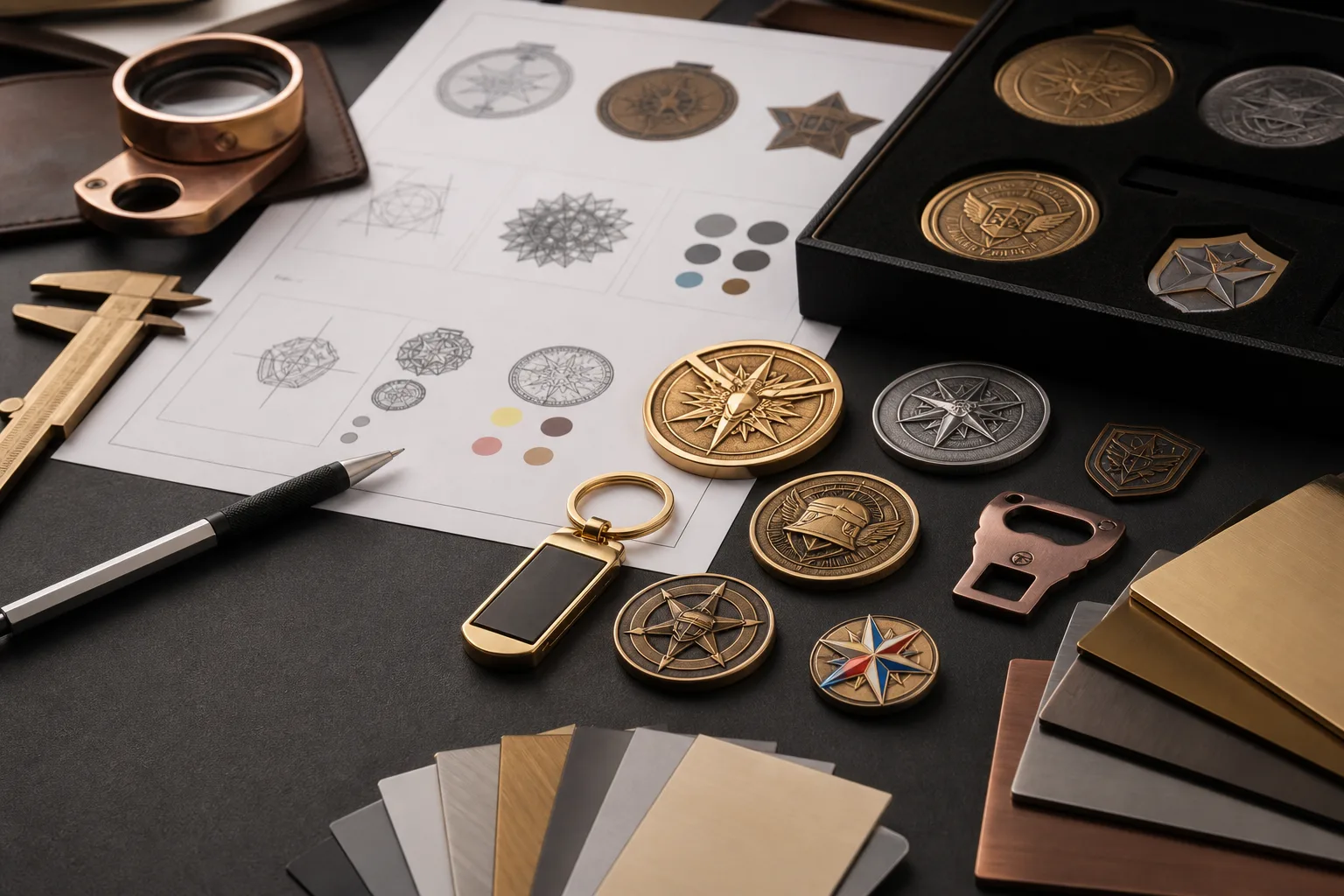
What to Include in Your First Artwork Package
A complete first submission gives our team a clear design map. It also helps us identify missing decisions without mistaking a visual reference for a confirmed instruction.
| Artwork item | What to provide | Why it matters |
|---|---|---|
| Source design | Vector file, PDF, clear image or labeled sketch | Shows the main concept and design elements |
| Product format | Medal, coin, pin, badge, trophy, plaque, keychain or bottle opener | Sets the context for the technical assessment |
| Dimensions | Overall width and height, plus intended thickness if known | Connects the artwork to the planned physical size |
| Quantity | Total quantity and any version breakdown | Identifies the commercial scope for later quotation review |
| Design views | Front, reverse and separate component views | Prevents hidden or reverse-side details from being missed |
| Decoration | Marked color areas, exposed metal, plating direction, print and epoxy notes | Shows where each visual treatment belongs |
| Content | Exact text, dates, names and correct logo versions | Provides a clear content record for the proof |
| Attachments | Type, position and orientation of ribbons, fittings, keyrings or other connections | Links the product body to its separate parts |
| References | Brand files, product photos or visual examples | Clarifies the intended appearance without replacing technical notes |
Mark any undecided item as open for review. Do not present a preferred dimension, color or component relationship as final unless your team has approved it internally.
Prepare Editable Vector Artwork Where Available
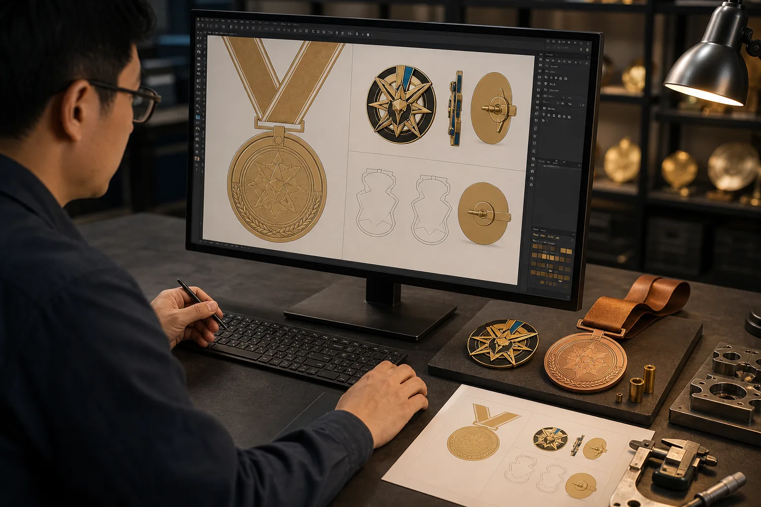
Vector artwork is built from editable paths, curves and shapes instead of a fixed grid of pixels. It can usually be enlarged without losing edge clarity. Editable paths also make it easier to inspect outlines, separate color areas and adjust design elements during proof development.
Gairun’s design engineering team uses Adobe Illustrator, CorelDRAW and AutoCAD for relevant 2D artwork tasks. We also use Rhino and ZBrush for relevant 3D development work. The software used to create a file does not by itself confirm that the design is ready for production. The content, structure and technical details still require review.
For a cleaner vector submission:
- Keep shapes, outlines and important design elements editable where possible.
- Supply the fonts used in the design or convert final text to editable vector outlines.
- Keep a separate text record so wording can still be checked after conversion.
- Separate colors and surface areas clearly instead of relying on small visual differences.
- Include linked logo files or images that are essential to the design.
- Label the current version so it is not confused with an earlier concept.
A flattened preview can accompany the source file. It gives reviewers a quick visual reference for how the editable elements should appear together.
Make PDFs and Image References Easy to Assess
A PDF can be useful for custom medal artwork, an enamel pin design file or another metal product concept when it clearly presents the intended design. However, a PDF may contain editable vector graphics, fixed-pixel images or both. The file extension alone does not confirm editability.
Orient each page correctly and make logos, wording, boundaries and labels easy to inspect. If the PDF contains several concepts, identify the selected version. If it contains front and reverse layouts, label each view rather than placing both designs on an unmarked page.
Clear image files may also support an initial review. Send the least compressed source available and avoid screenshots that hide fine text or crop the product boundary. When an image is only a visual reference, state that directly. Add written dimensions and color notes rather than expecting our team to measure or sample them from the image.
If you are unsure whether a file contains editable artwork, send the original design file with the PDF preview. Our team can check the available content and identify what may need to be redrawn through our artwork design and proofing service.
Turn a Rough Sketch into a Reviewable Product Concept
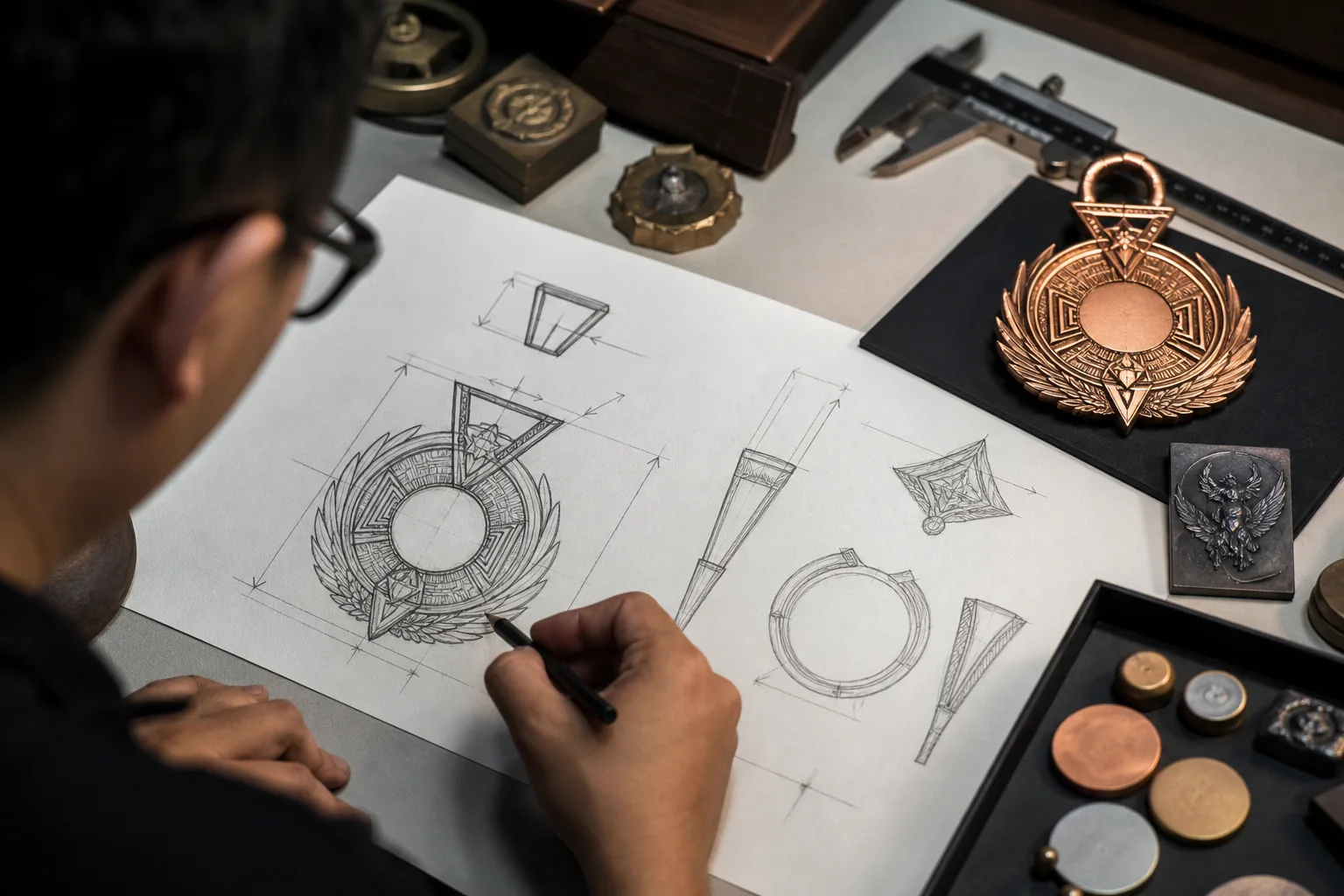
A hand drawing or rough digital sketch can start a technical discussion when finished artwork is not available. Gairun can work from simple vector sketches, PDFs and hand-drawn concepts to prepare 2D or 3D artwork for mold development. The design remains subject to technical review and buyer approval.
A useful sketch communicates relationships, not artistic polish. Draw the outer product shape and label the key features. Show the intended text, approximate size and main color areas. Mark which details should appear raised or recessed. If the design includes separate, connected or moving parts, draw each part and show how it relates to the main body.
Reference images can explain a pose, symbol, relief style or component arrangement that is difficult to draw. Identify which feature each image represents. This prevents a reference photo from being treated as the complete product specification.
Mark Size, Shape and Relief on the Design
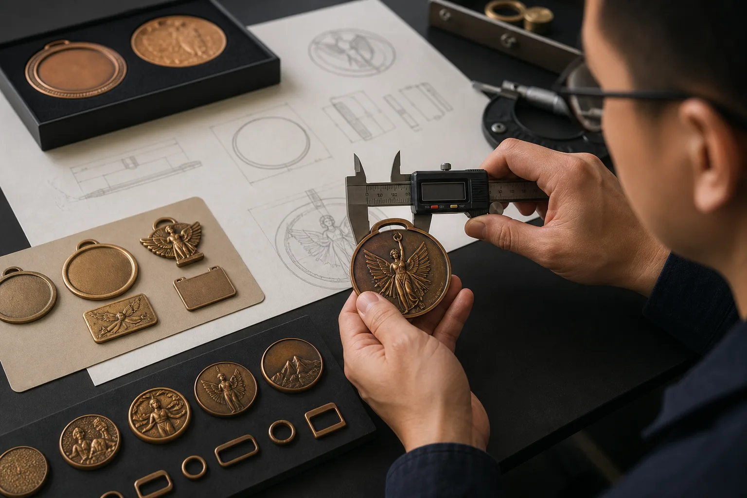
Physical dimensions connect a visual concept to a product that can be assessed for production. At minimum, mark the overall width and height. Add the intended thickness when your team has already made that decision. For an irregular outline, place dimension lines where they can be read without covering the artwork.
The design should also identify:
- The final outer shape and any open areas or cutouts
- Raised and recessed regions
- Areas intended as 3D relief
- Holes, slots and connection points
- Separate inserts or layered components
- The planned location of rotating or connected parts
Relief instructions should show which elements sit above or below surrounding areas. For a portrait, emblem or sculpted object, include another viewing reference if the front view does not explain the intended form. Spinning medals and combination structures need clear component boundaries and a marked center or connection relationship.
These notes are buyer-supplied design instructions for engineering review. They do not confirm final feasibility, production method or tolerance. Our team checks the proposed geometry before the design moves toward mold development.
Separate Color Areas from Metal and Surface Effects
Color instructions should identify each colored region and distinguish it from exposed metal or plating. A marked color map is more useful than an unmarked visual because similar shades may be difficult to separate on screen.
Provide named colors and brand color codes when they are available. Place each code beside the relevant area or use a numbered key. If a logo has a controlled brand file, include that file with the artwork package. Screen and device colors are visual references; they do not guarantee an identical physical result.
Different decoration methods require different artwork information. Enamel areas need visible boundaries. Screen-printed or UV-printed details should be identified as print rather than metal relief. If clear epoxy coating is intended, mark the coated area. For dual plating, show the boundary between the two metal tones without using the color map as a substitute for a finish specification.
This guide focuses on recording the design direction. For help comparing surface appearances, use the related guides in our buyer resource center.
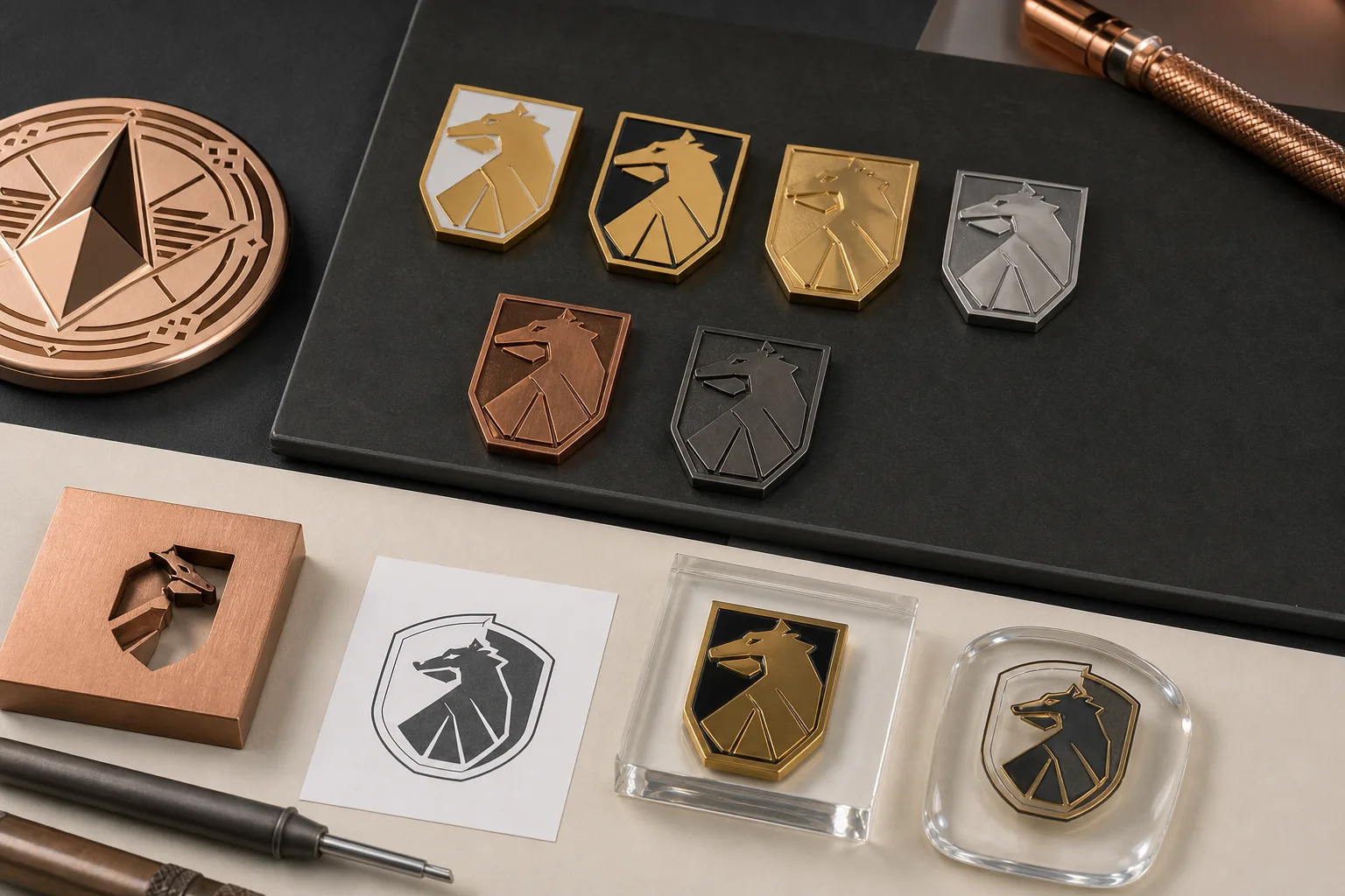
Show Front, Reverse and Separate Components
Provide a labeled view for every decorated or functional side. A front view does not tell our team what belongs on the reverse, and a single combined image may hide how separate components align.
For a two-sided medal or challenge coin, label the front and reverse and show their intended orientation. Mark repeated logos, reverse text and edge relationships. If the reverse should align in a specific direction when the front is upright, state that in the file.
Multi-part products need a component map. A spinning medal should show the fixed body and rotating center as separate artwork views. A combination award may need individual views for each metal element. Trophies and plaques should show how branded metal parts relate to the other visible components. Keychains and bottle openers should identify the product body, connection point and attached hardware.
You can review the available custom metal product formats to identify the closest product family, but the submitted artwork should still show the exact structure you intend.
Record Exact Text, Logos and Attachment Positions
Type all wording exactly as it should appear. Check spelling, capitalization, punctuation, dates and names before submission. If several product versions use different names or award levels, provide a clear version list rather than placing all alternatives over one design.
Supply the correct logo version and note any rules that affect its use. State whether text must remain editable or must match a supplied brand file. When converted outlines are included, add a plain-text copy for content checking.
Attachment notes should identify the part, position and orientation. For a medal ribbon, mark the ribbon connection point and show which direction the medal faces when suspended. For a lapel pin, state whether the design uses a butterfly clutch or strong magnet and mark its position on the reverse. For a keyring, show the connection location and intended orientation. Final attachment and assembly feasibility remains subject to engineering review.