
FACTORY-DIRECT OEM / ODM MANUFACTURING
Custom Metal Mold Making and CNC Engraving for Approved Designs
Gairun is an OEM and ODM metal crafts manufacturer that turns approved product artwork into tooling for custom medals, challenge coins, pins, badges, trophies, plaques, keychains and bottle openers. We support event organizers, institutions, brands, award suppliers and promotional product wholesalers that need clear control between design approval and metal production.
Our custom metal mold making and CNC engraving process follows a defined path: the engineering team reviews the approved 2D or 3D design, develops the mold geometry, engraves the tooling, produces a trial-formed part and compares the first article with the approved drawing. This sequence lets design and sourcing teams review how dimensions, thickness and relief details have transferred into a physical metal part before the project moves forward.
Gairun operates a dedicated mold-making and CNC engraving studio within its Shenzhen production operations. To begin a tooling review, send your product design, dimensions, structure and order requirements through our request-a-quote form.
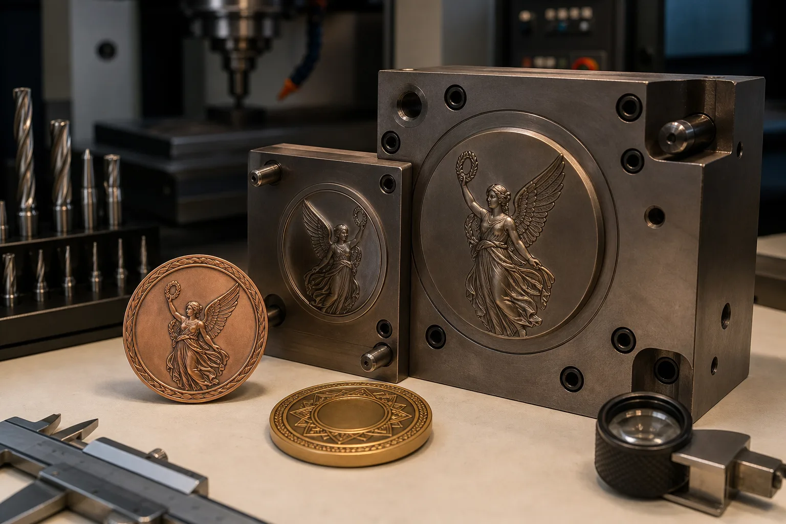
How Production Tooling Connects Artwork to Formed Metal
A mold is the production tool that carries the defined shape and surface geometry of an approved design into a formed metal part. Depending on the product, that geometry may include the outer profile, lettering, borders, recessed fields, raised emblems and sculpted relief.
CNC engraving is the machine-controlled process used to develop these features in the mold. The CNC engraving machine follows digital geometry prepared from the approved design. This creates the tooling features needed to reproduce logos, text, outlines and relief during trial forming and later production.
Tooling sits between design approval and the selected metal-forming operation. It does not decide the artwork or the full production route by itself. Those choices must be settled through an engineering and design-for-manufacturing review before mold development begins. Buyers comparing the full sequence from tooling through finishing can review our broader manufacturing capabilities.
What Must Be Defined Before Mold Development Starts
Mold work should begin from a controlled production design rather than an open concept. A project may start with vector artwork, a PDF or even a hand-drawn sketch, but the design must be reviewed and converted into an agreed 2D or 3D production reference before tooling.
The design handoff normally needs to define:
- Product family: medal, coin, pin, badge, trophy, plaque, keychain, bottle opener or another declared structure.
- Physical format: overall dimensions, thickness, outer shape and front and back views.
- Surface geometry: raised, recessed, level, layered or sculpted areas and the intended relief direction.
- Design content: final logos, lettering, dates, borders and other fixed visual elements.
- Component relationships: attachments, separate parts, rotating sections and the way connected pieces relate to one another.
- Appearance direction: intended color areas and metal finish direction where these choices affect the tooling layout.
Gairun*s engineering team works with AutoCAD, CorelDRAW, Adobe Illustrator, Rhino and ZBrush for 2D and 3D design preparation. These tools support the handoff from the visual design to the digital geometry used for mold development. Buyers who are still preparing source files can use our artwork and file preparation guide before requesting a tooling review.
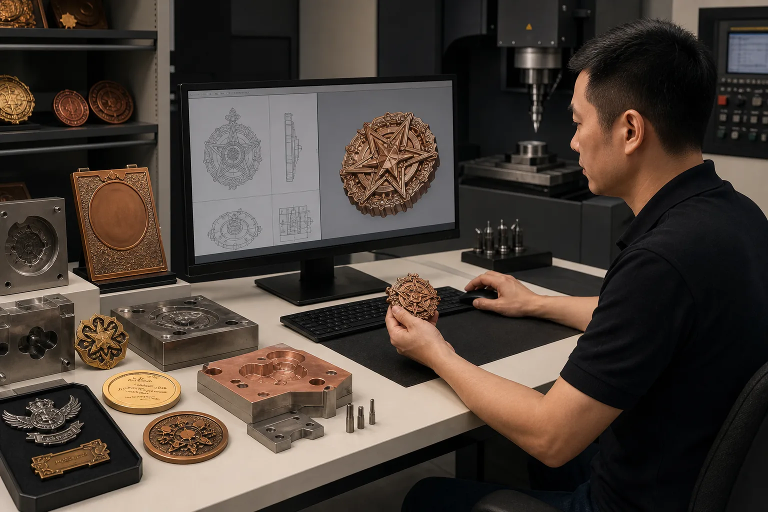
Converting Logos, Lettering and Relief into Mold Geometry
A flat image does not automatically describe how each feature should exist in metal. During mold development, the design is interpreted as a set of raised, recessed and level areas. The relationship among those areas controls how the main emblem, supporting text, borders and background are represented on the tooling.
Visual hierarchy is important. A primary logo may need to stand apart from a background field, while small lettering needs a defined relationship with nearby borders and relief. In a sculpted design, the tooling geometry must also represent gradual changes in form rather than only separate flat levels. The engineering review considers these relationships without assuming that every detail in the source image can transfer unchanged.
Front-and-back designs require coordinated geometry on both faces. Multi-part products add another level of planning because each molded component must follow the component map and support the intended assembled structure. The product structure and selected forming route can therefore change the tooling plan. Specific decisions about casting, stamping or hydraulic forming are handled within the relevant production review rather than by artwork appearance alone.
CNC Engraving for Custom Award and Promotional Product Tooling
Gairun uses CNC engraving machines in its mold-making and CNC studio to develop production tooling from the prepared digital geometry. CNC means computer numerical control. In this process, programmed machine movement follows the defined geometry used to create the required mold features.
The purpose is controlled reproduction of the approved design structure. The engraved mold must carry the features needed for the product profile, logo shapes, letter forms, border lines and relief surfaces. CNC engraving is especially relevant when a project contains several relief levels, sculpted details or coordinated front-and-back content.
Digital preparation and physical engraving remain connected throughout the tooling stage. If the approved geometry changes, the tooling scope must be reviewed again. This link between design version and mold version helps prevent an outdated logo, text block or component layout from moving into trial forming.
Machine brands, machining tolerances, tooling materials and mold lifespan depend on technical details that are not defined as universal values. Gairun reviews the actual product design instead of assigning an unsupported accuracy or tooling-life claim to every project.

How Product Structure Changes the Tooling Plan
The same tooling approach does not fit every custom metal product. Shape, relief style, number of faces and component count all influence how the mold geometry is organized. Buyers can compare the main product families through our custom metal products hub, while the table below shows the tooling questions created by different structures.
| Product or structure | Tooling input to define | First-article focus |
|---|---|---|
| Medals and challenge coins | Outer profile, front and back content, lettering and relief hierarchy | Overall dimensions, thickness and relief reproduction |
| Pins and badges | Small logo elements, borders, text and attachment relationship | Defined geometry and correspondence with the drawing |
| Trophies and plaques | Metal component shape, branded features and relationship to other parts | Component dimensions and relief detail |
| Keychains and bottle openers | Product outline, branded area, openings and connected components | Shape, thickness and feature placement |
| Sculpted 3D relief | Viewing form, relief transitions and feature hierarchy | Transfer of sculpted details into the physical part |
| Rotating or combined medals | Separate component map, front and back views and moving relationships | Individual parts and their intended relationship |
A flat or layered design can use clearly separated height levels. Sculpted 3D relief uses changing surfaces to create a more dimensional form. A rotating or combined medal may require separate tooling plans for different components. The final approach depends on the reviewed design and the selected production route.
Checking the Trial-Formed First Article Against the Drawing
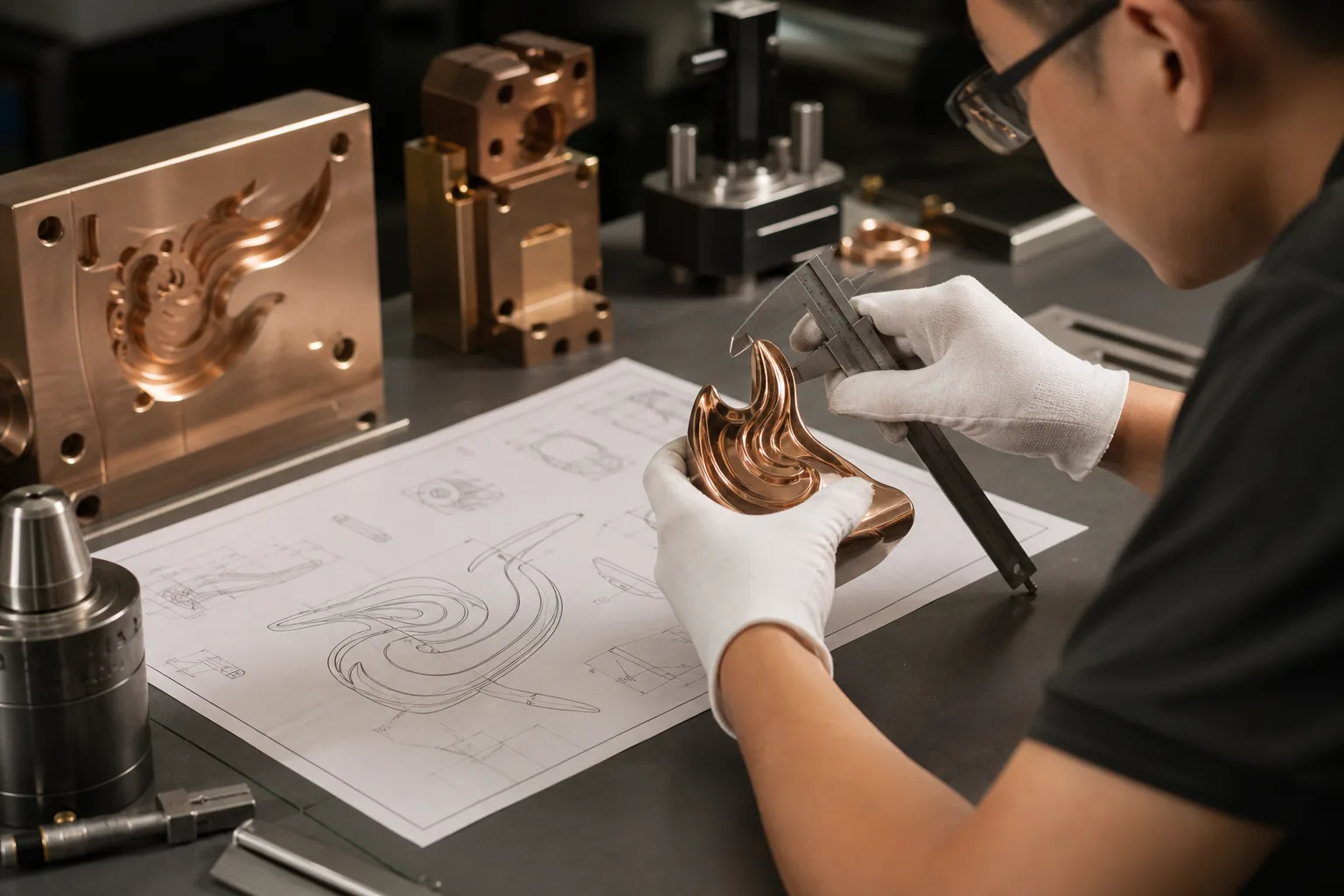
After mold engraving, a trial piece is formed so the team can compare a physical result with the agreed design. This first article provides evidence of how the tooling has transferred the defined product geometry into metal.
Gairun*s verified first-article sequence is:
A 1:1 drawing comparison means that the first article is checked against the production reference at full scale. It keeps the review tied to the agreed product design rather than to a general visual impression. No single acceptance tolerance is stated for all products; project requirements need to be defined and reviewed for the specific design.
This check is focused on tooling reproduction. Broader incoming material inspection, in-process checks, finished-product inspection and physical testing are covered under Gairun*s separate quality control process.
01
The mold is engraved from the reviewed digital geometry.
02
A trial pressing produces the first physical part for comparison.
03
The part is checked through a 1:1 comparison with the approved drawing.
04
Dimensions, thickness and relief detail are reviewed against that drawing.
Managing Tooling Corrections and Buyer-Led Design Changes
If the trial-formed part does not match the approved drawing, the team identifies whether the difference comes from tooling reproduction or from an unclear design instruction. The required action is then reviewed against the controlled drawing and tooling version.
A tooling correction is not the same as a buyer-led artwork revision. A correction addresses how the existing approved geometry appears in the trial part. A design revision changes the intended result, such as replacing text, changing relief, moving a border or altering a component relationship. That type of revision may change the tooling scope and requires renewed engineering review before work continues.
Written approval and version control are important at this stage. File names, drawing versions and change comments should make it clear which design controls the tooling. This is especially important for front-and-back products, several design variants and multi-part structures where one change may affect connected components.
The number, timing and commercial effect of corrections cannot be set without reviewing the project. Keeping tooling corrections separate from new design requests gives sourcing teams a clearer record of scope and approval responsibility.