
A production-ready zinc die-cast badge begins with surface priorities, not just an attractive 3D rendering. Before tooling, identify the critical face, decide how raised and recessed forms should read, and place the die casting parting line where seams, ejector evidence, and cleanup are least disruptive. The same logic helps buyers compare a dimensional zinc-alloy design with flatter routes such as Soft Enamel Pins.
This zinc die casting DFM guide explains how those choices connect. It avoids universal limits for feature size, relief depth, draft, wall thickness, and radii because the correct values depend on the alloy, tool, geometry, decoration plan, and acceptance criteria. Use the framework below to prepare a clearer supplier discussion before mold work.
Start With a Surface-and-Relief Decision Framework
Begin by classifying every face and feature before finalizing the 3D model. Mark each surface as critical visible, secondary visible, functional, hidden, or sacrificial. Then rank the visual hierarchy: dominant relief, supporting relief, recessed background, border, edge, and non-cosmetic tooling areas.
This prevents a common design error: treating every line and level as equally important. A die-cast part must open, eject, be cleaned, and receive its finish. A feature that looks impressive in a rendering may need a different transition or decoration method in a real part.
| Observable input | Practical implication | Initial decision | Still to confirm |
|---|---|---|---|
| One dominant raised emblem with a broad recessed field | The main subject should remain visually clear after cleanup and finishing. | Prioritize one strong relief hierarchy and keep tooling evidence away from the emblem. | Reverse-face geometry, attachment position, plating contrast, and acceptable seam locations. |
| Fine lettering crossing a raised border and recessed background | Several height changes may compete with legibility and polishing access. | Simplify the lettering or move it away from the sharpest transition. | Artwork scale, viewing distance, finish, and whether printing is more suitable. |
| Irregular outer silhouette with dimensional side features | Tool-opening direction and ejection may affect the edge and side appearance. | Set the silhouette and relief direction together before detailing the face. | Undercuts, draft, attachment clearance, and acceptable edge evidence. |
| Two cosmetic faces with different relief systems | One face may constrain the other during tool layout and ejection. | Define front-to-back relationships as one structure. | Tool members, ejector locations, thickness distribution, and appearance criteria. |
Gairun’s pre-tooling engineering review may cover dimensions, thickness, relief, metal borders, color areas, attachments, component positions, and the proposed production method. The exact checklist changes with the product structure and artwork. Gairun lists zinc-alloy die-casting alongside stamping, photo etching, and hydraulic high-relief forming, but these routes are not interchangeable.
Example 1: A souvenir badge has an irregular landmark outline, one raised landmark, and a recessed background. The initial decision may favor zinc alloy die-casting because the outline and dimensional relief are central to the design. A simpler flat pattern with fine printed detail could instead favor another forming or decoration route. Artwork scale and the intended finish could change the decision.
Example 2: A corporate badge has a clean border and small lettering distributed across several levels. The initial decision may be to simplify the relief and preserve a broad, readable text area. The recommendation could change if the badge is larger, viewed closely, or finished with a print method rather than relying on molded detail.
Do not borrow a numeric limit from a general chart without checking the actual alloy, tooling approach, part orientation, and finish. Feature size, relief depth, draft, wall thickness, and transition radii need engineering confirmation for the proposed design.
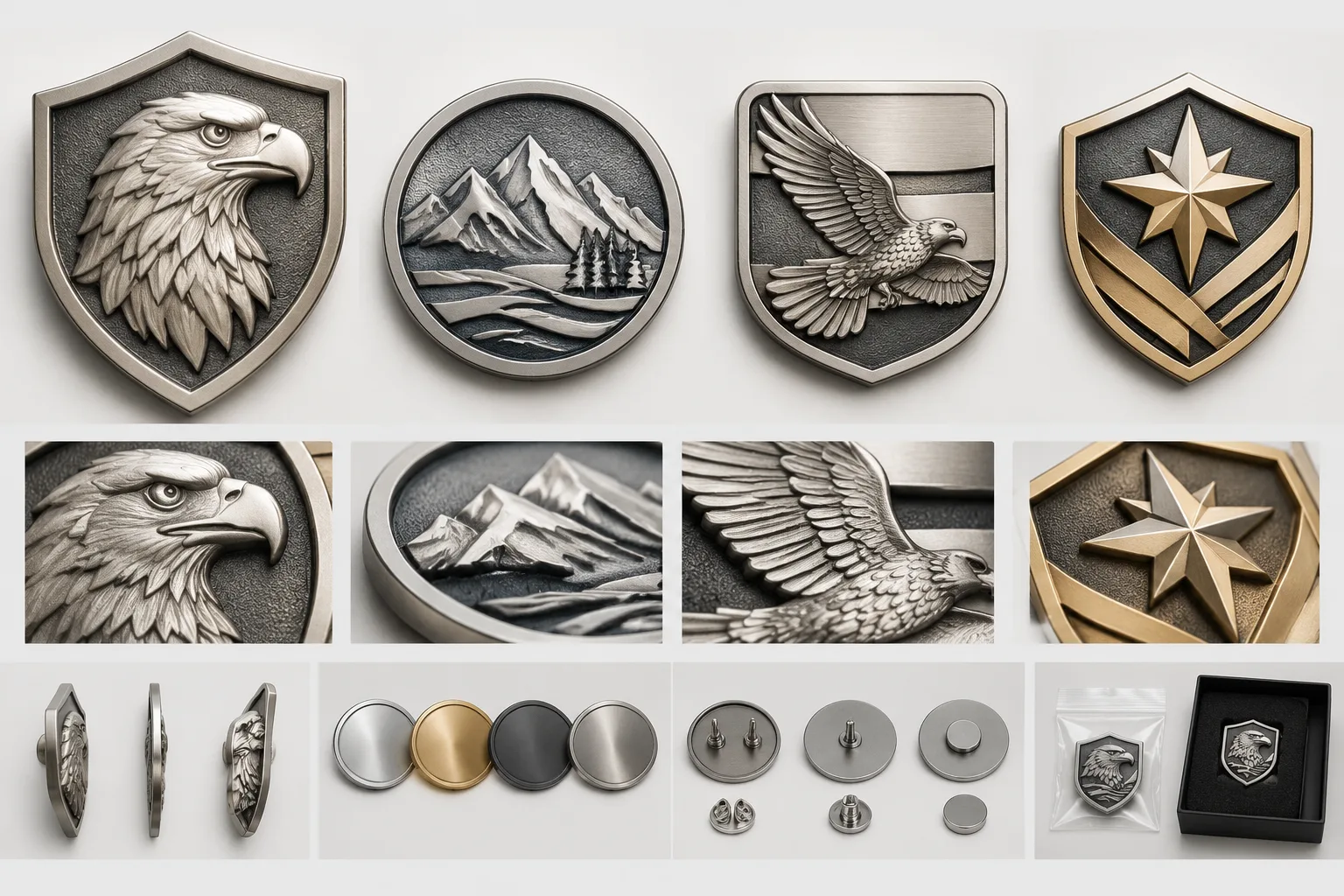
Mark Critical and Cosmetic Surfaces Before Tooling
Surface classification affects tool layout, parting-line strategy, ejector placement, cleanup, and appearance approval. Mark the front, reverse, outer edge, border, recesses, attachment area, and any surface that becomes visible after assembly or while the badge is worn.
Separate cosmetic requirements from functional ones. A reverse attachment pad may not need the same visual standard as the front emblem, but it can still affect front-face distortion, balance, or how the part sits on fabric. Conversely, a narrow front border may be visually important even though it has no functional role.
- Identify where a seam, ejector witness, gate-related evidence, flash, or polishing variation is unacceptable.
- Define whether slight tonal contrast is acceptable under the selected plating, matte treatment, or color fill.
- State the viewing direction, lighting conditions, handling distance, and whether the product is inspected individually or in a group.
- Keep critical logos, lettering, narrow borders, and fine lines away from areas likely to need aggressive cleanup unless the tool and finish plan support them.
- Use a marked-up drawing or 1:1 visual reference so appearance priorities are not confused with general design intent.
Gairun describes burr inspection, polishing, flatness checks, and cleaning before decoration. That process does not create a universal roughness, flatness tolerance, or cosmetic grade. Your purchase specification should identify acceptable locations and defect limits instead of relying on the phrase “high quality.”
A custom sample can show the proposed appearance and construction. Sample approval remains separate from authorization for bulk production. This distinction matters when the finish, attachment, artwork, or packaging changes after the sample.
For technical background, the zinc die-casting parting-line design guidance explains why shutouts and maintainable die members influence seam placement. The principle is practical: a visually ideal seam location may not be the most stable tool arrangement, so the supplier should show the compromise before tooling.
Build a Clear Relief Hierarchy for Zinc Die Casting
Convert flat artwork into an ordered relief map. Identify the dominant subject first, then supporting forms, background fields, borders, edge details, and text. Each element should have a clear front-to-back relationship.
Adjacent raised and recessed details should not compete when there is no useful transition or cleanup area between them. A strong design usually gives the primary subject the clearest height and contrast, while secondary details support it through smaller relief changes, color, matte treatment, or print.
- Dominant subject: the feature that must remain recognizable at the expected viewing distance.
- Supporting relief: forms that create depth without overpowering the subject.
- Recessed field: an area that separates the main relief and can receive color, matte treatment, or antique contrast.
- Border and edge: structural and visual boundaries that may also conceal tooling evidence.
- Fine artwork: lines, lettering, gradients, and small marks that may be molded, recessed, printed, or omitted.
Gairun describes 3D relief as a hierarchy of raised and recessed forms. For zinc-alloy die-cast pins, formed outlines, irregular bodies, and dimensional relief can be considered, but every small feature should not be expected to transfer unchanged. A 2D or 3D proof is a visual checkpoint before mold work when sufficient information is available; it does not replace confirmation of dimensions, structure, finish, or order terms.
Submit an annotated 3D proof or relief map. Use arrows, levels, or plain-language notes to show which forms sit forward and which remain recessed. A flat file alone can leave the supplier guessing about whether a line represents a groove, a border, a color boundary, or a printed detail.
Fine lettering deserves special caution. If it crosses a high-relief transition, moving it to a flatter field may protect legibility. If the artwork contains multiple tones, gradients, or very fine marks, UV printing may address the graphic requirement differently from molded relief. Gairun offers UV printing for printed detail or multiple tones, but fine marks and color layout still need an artwork check.
Review the Die Casting Parting Line and Ejection Visibility
The principal tool-opening direction should be chosen around the dominant silhouette, primary cosmetic face, relief direction, and attachment geometry. Then test where the parting line, ejector contacts, flash, and cleanup access could appear.
When the design permits, place the die casting parting line along a border, edge, recess, or later assembly feature. Avoid crossing a prominent logo, face, narrow lettering, or high-contrast finish area. This is a preference, not an automatic rule: the tool must still close, support the geometry, and release the part reliably.
Undercuts, enclosed recesses, deep pockets, and side features can require separate die members or other tooling decisions. The technical guidance on die-opening direction and undercuts explains why removable geometry and retracting die pieces must be considered during design.
Ask for a tooling sketch that identifies:
- the proposed opening direction;
- the parting-line path;
- possible ejector contact areas;
- features that may need slides or separate die members;
- areas where flash or cleanup could affect appearance; and
- any relief or transition changes needed for release.
Gairun states that its mold-making and CNC engraving workshop develops tooling that defines shape, dimensions, thickness, and relief. After trial forming, its stated first-article process compares dimensions, thickness, and relief detail with the approved 1:1 drawing. That check does not establish project tolerances or prove that every seam location will be acceptable, so the cosmetic acceptance plan must remain separate.
Do not treat a clean rendering as evidence that the tool can open, eject, and finish the part without modification. Polishing, plating, painting, and color filling can make a small seam more visible or less visible. Decide this against an approved sample or defined reference condition.
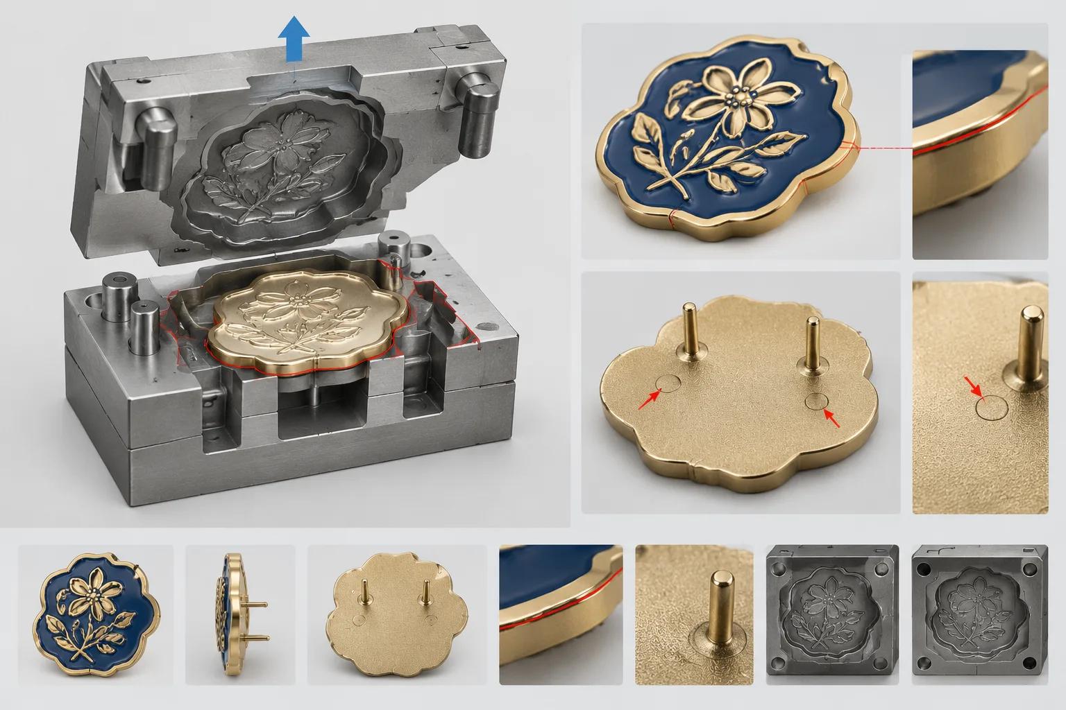
Manage Transitions, Edges, Recesses, and Attachments as One Structure
Local geometry decisions affect filling, release, cleanup, assembly, and appearance together. Inspect abrupt changes between thick and thin areas, raised fields and flat backgrounds, narrow borders, sharp corners, and deep recesses as connected features.
Useful transitions preserve the relief hierarchy while reducing isolated peaks, fragile edges, trapped details, and difficult polishing access. The outer edge also deserves attention. A crisp outline may support the design, but it can expose flash, increase plating visibility, or create a less comfortable edge during handling.
Rear attachments should be included in the same engineering package. Define the pad, post, pin, magnet, or other component position before tooling if it may affect front-face distortion, balance, or visible assembly. Moving or combination products need alignment, connection points, and clearances checked as an assembled system rather than inferred from front artwork.
For a uniform badge used on employee clothing, one Gairun scenario identifies zinc alloy, a maximum dimension of 25–45 mm, and a base body thickness of 1.5–2.5 mm. It also lists die casting or stamping among possible processes. These values describe that uniform-badge use case, not universal zinc die-casting limits.
In the same scenario, attachment selection depends on fabric thickness, wearing direction, weight, and surface treatment. Dual-pin butterfly backs, screw posts, or magnetic backs may be considered. Needle components need protection against puncture. Magnetic attachments require attention to medical-device warnings and child ingestion risk. Where relevant, validate wear stability, fabric pull, and back retention.
The correct structure may also influence whether zinc alloy is the best route. Gairun lists zinc-alloy die-casting, die-struck forming, photo etching, and hydraulic high-relief forming. Material, shape, relief structure, text, color layout, and decoration should determine the comparison.
Design for Polishing, Plating, and Cosmetic Contrast
Forming is only one part of the appearance decision. Before approving the model, decide whether the design needs polished highlights, matte or sandblasted fields, antique contrast, plated metal areas, color-filled recesses, or printed detail.
Polishing access may differ across raised faces, recesses, edges, and internal corners. A narrow border can lose definition if the finishing route visually merges adjacent levels. A deep recess may retain contrast but be harder to clean consistently. These effects should be assessed against the artwork hierarchy, not selected by finish name alone.
Gairun lists gold, silver, nickel, black nickel, antique bronze, and antique silver as plating directions. The final tone and feasibility must be coordinated with the base metal, relief, artwork, and exposed areas. A plating color does not establish precious-metal purity, thickness, gloss, corrosion performance, or durability.
Gairun also lists sandblasting and matte finishing for reducing shine or creating contrast. Exact texture and gloss require an approved specification or sample. Its stated surface-preparation flow includes burr inspection, polishing, flatness checks, and cleaning before decoration, but it does not establish a universal cosmetic grade.
| Artwork priority | Possible treatment | What to watch |
|---|---|---|
| Strong dimensional subject with clear background | Molded raised and recessed relief with contrasting metal finish | Polishing access, border definition, and seam visibility. |
| Smooth color fields close to one level | Imitation hard enamel, which brings color and metal areas closer to one level | Controlled color boundaries and metal borders. |
| Fine marks, gradients, or multiple tones | UV printing for printed detail | Artwork scale, color layout, and project-specific appearance approval. |
| Low-glare field beside polished highlights | Matte or sandblasted treatment | Texture consistency and the width of treated areas. |
Where fine artwork matters more than dimensional relief, compare zinc die-casting with another forming or decoration route. For broader product comparisons, buyers can also consult Gairun’s Metal Materials Comparison while keeping the final decision tied to the actual geometry and finish.
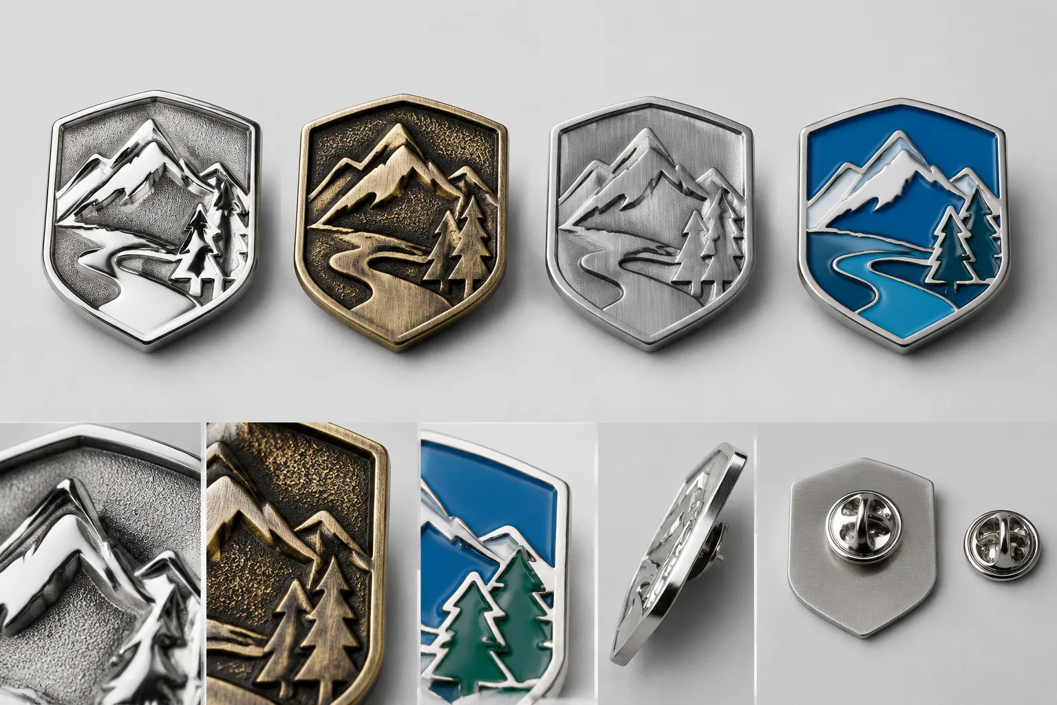
Use a Pre-Tooling Zinc Casting Design Review Checklist
A controlled handoff reduces ambiguity before mold work. Send the product format, material direction, dimensions, thickness intent, front and reverse artwork, relief map, attachment details, finish, color areas, and packaging needs when relevant.
- Mark critical cosmetic surfaces and acceptable locations for seams, ejector evidence, gates, polishing variation, and plating contrast.
- Ask the supplier to return a drawing showing opening direction, proposed parting line, ejection contact areas, relief interpretation, transition changes, and unresolved features.
- Approve production artwork before tooling. Keep engineering, sample, commercial, testing, packaging, and shipment decisions separate.
- If a custom sample is selected, compare it with the approved 1:1 drawing and appearance reference before authorizing bulk production.
- Define actual tolerances and acceptance criteria separately from the artwork. Use first-article inspection to check the agreed dimensions, thickness, and relief detail.
- For an RFQ, include product type, quantity, dimensions, artwork, variants, finish, color treatment, attachments, packaging, destination, and required schedule. Mark unresolved technical choices as open for discussion.
Gairun describes a connected service path from requirements and artwork engineering through sample planning when selected, production coordination, packaging, and shipment preparation. Not every order requires a custom sample. A 50-piece trial order may be supported for selected products, subject to design, process, and project review; it is not a universal minimum order quantity.
Gairun states that its forming equipment includes 88-ton and 160-ton zinc-alloy die-casting machines. Machine tonnage alone does not establish production capacity, part size, tolerance, or suitability. Formal confirmation is still needed for the proposed part.
Packaging should be specified with the surface and distribution plan. Gairun lists anti-scratch packing, individual OPP bags, bubble protection, velvet boxes, paper display boxes, and plastic display boxes. The suitable format depends on surface exposure, presentation, product dimensions, and shipping needs. Do not assume every option is included or suitable for every badge.
For a concise zinc casting design review, provide the model and relief map together with the marked-up cosmetic drawing. That package lets the supplier connect tooling, ejection, finishing, attachment, inspection, and packaging decisions before production authorization.
FAQ
Where should the die casting parting line go on a badge with a visible front face?
Prefer a border, edge, recess, or later assembly feature when the tool design permits. Avoid prominent logos, lettering, faces, and narrow decorative lines. The final location must balance appearance with tool closure, release, and maintainability.
How should raised and recessed relief be prioritized in a zinc die casting DFM review?
Identify the dominant subject first, then supporting relief, recessed background, border, edge, and fine detail. Use an annotated relief map that shows the front-to-back order. Do not give every feature equal height or visual priority.
Can fine lettering or small artwork be reproduced unchanged in a zinc die-cast part?
Not automatically. Small details may need simplification, relocation, printing, or omission. Artwork scale, viewing distance, relief transitions, finish, and decoration method determine the practical treatment.
How should ejector marks, flash, and parting-line evidence be handled on cosmetic surfaces?
Mark acceptable and unacceptable areas on a 1:1 drawing. Request the proposed opening direction and ejection locations before tooling, then define viewing conditions and defect limits for sample or first-article approval.
What information should a buyer provide for a zinc casting design review before tooling?
Provide product type, quantity, dimensions, front and reverse artwork, relief hierarchy, material direction, finish, color areas, attachments, packaging, destination, and schedule. Include critical cosmetic surfaces and identify unresolved choices.
When should a zinc die-cast badge use a custom sample or first-article approval?
Use a custom sample when appearance, relief, attachment, or finish carries meaningful risk. First-article inspection should compare the formed part with the approved 1:1 drawing for agreed dimensions, thickness, and relief detail. Define tolerances and appearance criteria separately.