
Choosing between a 2D proof and a 3D rendering depends on the risk you need to remove first. A 2D production artwork proof confirms visible graphic information such as wording, logos, color areas, orientation, and layout. A 3D product rendering adds spatial information, including relief, thickness relationships, edges, layers, and component positions. Gairun’s Artwork Design and Proofing process uses either format as a visual control point when sufficient project information is available.
The practical rule is simple: start with 2D when identity and graphic placement are uncertain. Start with 3D when structure and depth are the main concern. Many complex custom metal products require both. Neither approval alone confirms every engineering, material, finish, attachment, packaging, testing, commercial, or shipment requirement.
2D Proof vs 3D Rendering: Which Approval Do You Need First?
Use a 2D proof first when the design is relatively flat and the main questions concern what the product should say or display. This is common for printed metal badges, flat graphic treatments, die-struck designs, and color layouts where the silhouette and construction are already understood.
Use a 3D rendering when a buyer could misunderstand the product by looking only at a flat front view. Relief medals, irregular outlines, multi-layer pieces, rotating parts, magnetic components, and assembled products benefit from views that show depth and relationships between parts.
| Primary risk | Most useful first approval | What the buyer can inspect | What remains open |
|---|---|---|---|
| Incorrect wording, logo placement, or color division | 2D proof | Spelling, orientation, front and reverse layout, borders, openings, and color regions | Fine-feature feasibility, material, thickness, attachment, and finish behavior |
| Unclear raised and recessed hierarchy | 3D rendering | Silhouette, relief levels, edge shape, thickness relationships, and angled presentation | Actual forming result, tolerances, surface texture, and final color behavior |
| Multiple parts or a moving center | Both, followed by engineering or sampling | Graphic content in 2D and component relationships in 3D | Clearance, fit, retention, movement, testing, and protective packaging |
| Appearance and construction cannot be judged on screen | Physical sample | Buyer-specific appearance, construction, attachment, and finish together | Any later change to artwork, structure, packaging, or production quantity |
At Gairun, the proof is a controlled reference for later tooling and sampling decisions. Tooling begins only after the relevant production artwork has been reviewed and accepted. That acceptance does not approve commercial terms, testing, packaging, shipment terms, or every engineering assumption.
What a 2D Production Artwork Proof Actually Confirms
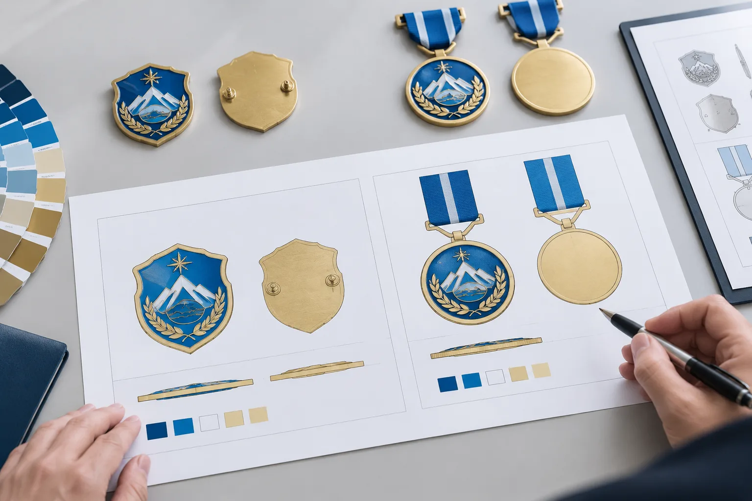
A 2D production artwork proof is a flat, production-facing view of the proposed design. It should make the visible content unambiguous before tooling or other downstream decisions begin.
- Exact wording, spelling, dates, names, ranks, and service messages
- Authorized logos, emblems, and other supplied identity elements
- Front and reverse artwork, including orientation and text direction
- Overall dimensions, proportions, design variants, borders, and openings
- Color regions, print areas, enamel areas, plating instructions, or other visible treatments
- Attachment positions, such as pin posts, backs, loops, or other specified hardware
- Whether the artwork matches the intended product format
For official government, military, and public-safety designs, the buying team should identify who is authorized to supply the emblem or wording and who has final approval authority. A supplier should not assume authorization simply because artwork has been provided.
Gairun can begin artwork review from vector artwork, a usable PDF, or a hand-drawn concept. These are starting inputs, not automatic production approvals. Dimensions, wording, color references, front and back instructions, attachments, and the intended product format should accompany the file whenever available.
A 2D proof is particularly useful for a die-struck badge, printed metal badge, or flat enamel layout. It shows whether the visible design is arranged correctly. It does not prove that every small line, narrow gap, text character, or color transition can be formed or decorated as drawn. Those details need to be considered with the selected material, process, scale, and geometry.
Once accepted, the production artwork should become the controlled reference. If a buyer later changes text, dimensions, attachment position, relief, finish, or packaging, that change should be recorded as a new approval decision.
What a 3D Product Rendering Adds to the Approval
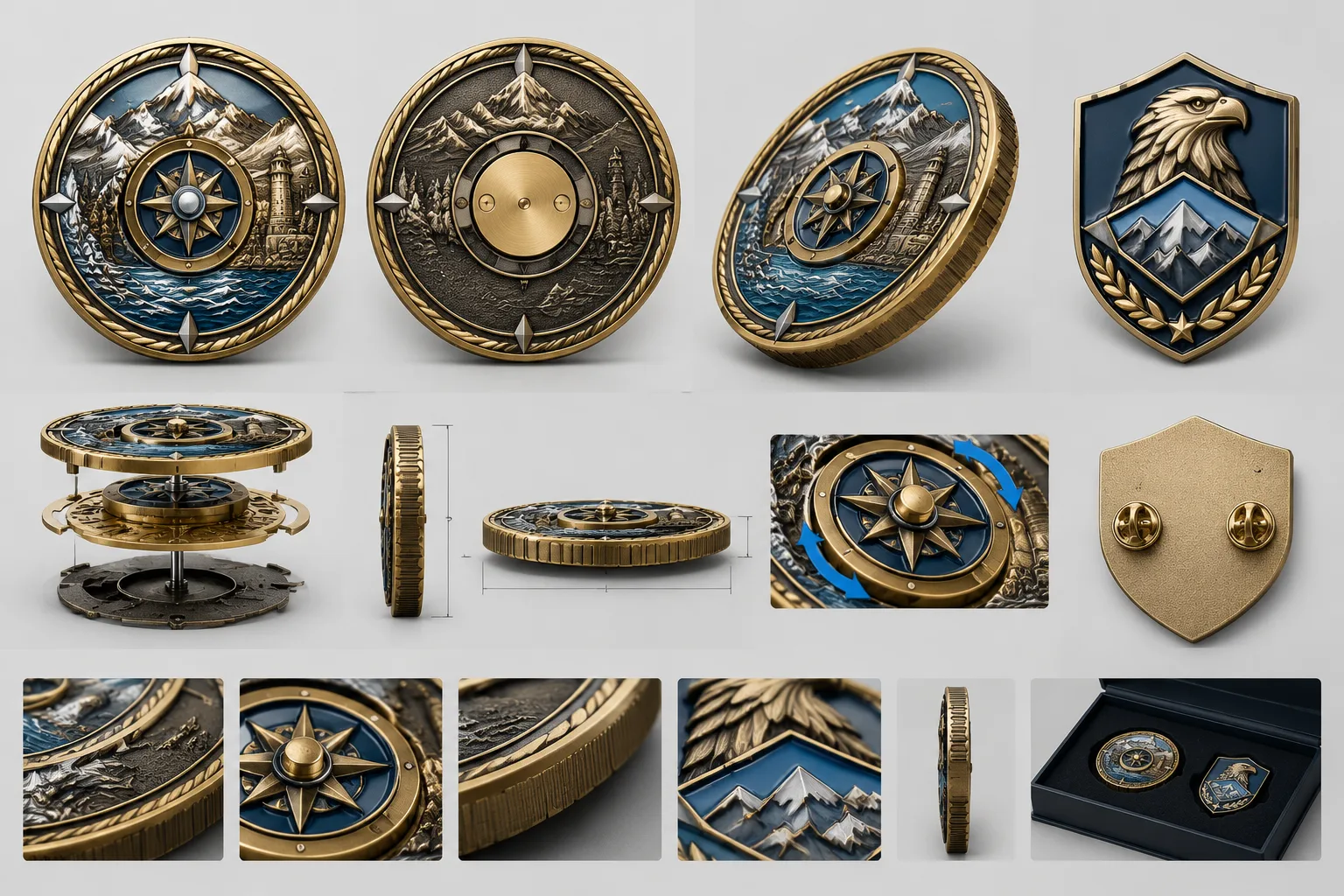
A 3D rendering communicates the product as a structure rather than only as a graphic. It helps buyers inspect the overall silhouette, thickness relationships, relief hierarchy, raised and recessed areas, edge treatment, component overlap, and front-to-back alignment.
For a 3D relief medal, the design brief should identify which forms sit forward and which fields remain recessed. Sculpted relief is a hierarchy of levels, so a rendering can expose a confusing transition that may not be visible in a front-facing 2D layout.
Challenge coins require the same discipline. The border, edge, thickness, front face, and reverse face should be planned together. A coin may look correct from the front while the reverse text is inverted, the edge direction is inconsistent, or the border does not continue cleanly around the structure.
For multi-layer or moving concepts, use the rendering to clarify assembly order and the distinction between the base body and assembled thickness. It should show openings, rotating or removable parts, magnets where used, and the way components overlap or align.
A rendering improves spatial communication, but it remains a representation. It does not prove actual metal flow, final surface texture, color behavior, fit, tolerances, long-term function, or attachment retention. Fine artwork may also need to be simplified or reorganized before it can transfer into 3D relief or die-cast construction.
Gairun’s pre-tooling engineering review may cover dimensions, thickness, relief, metal borders, color areas, attachments, component positions, and the proposed production method. The exact checklist depends on the artwork and product structure. A 3D product rendering supports that conversation; it does not replace it.
Match the Proof Type to the Product Structure
The correct proof path depends more on structure than on the product name. Gairun works with several construction routes for pins and badges, including enamel, die-struck, zinc-alloy die-cast, photo-etched, and printed designs. These routes are not interchangeable because artwork, surface appearance, shape, relief, text, color, and attachment requirements change the decision.
Material selection also needs to be considered with geometry, forming method, relief, decoration, and intended use. Gairun lists zinc alloy, brass, iron, stainless steel, and aluminum among the metals it can process for custom products. The suitable option must be confirmed for the particular construction rather than selected from a material list alone.
For a complex challenge coin scenario, a 45–60 mm collector-oriented concept with a 4–6 mm base thickness and possible 5–9 mm assembled thickness may justify an initial 3D rendering. These figures are scenario guidance, not universal specifications. A design with rotating, magnetic, detachable, or layered parts should also confirm the structure drawing, base and total thickness, moving-part tolerances, magnet specification where used, drop testing, and protective packaging.
For an employee or service badge scenario, a 2D proof may settle identity and text placement first. A 25–45 mm size range and 1.5–2.5 mm base-thickness range may be considered for that type of application, but the buyer must separately confirm the actual size, material, weight, surface treatment, wearer orientation, fabric thickness, and attachment choice. Deep relief, a curved surface, an irregular outline, or a die-cast dimensional body may make 3D review more useful.
A custom sample, when selected, is made for the buyer’s artwork to inspect proposed appearance and construction. Sample approval remains separate from authorization for bulk production. The initial recommendation can change when the buyer changes relief, movement, attachment, material, intended use, or required validation.
Two Buyer Examples: How the Initial Recommendation Can Change
Example 1: Commemorative challenge coin with moving center
This hypothetical concept has a portrait, front and reverse text, a sculpted emblem, and a rotating center. Begin with a 2D proof to settle wording, orientation, front and reverse artwork, and color placement. Then use a 3D rendering to inspect relief hierarchy, border continuity, edge direction, center clearance, and the relationship between the moving part and base body.
The unresolved variables include the actual movement, retention method, total assembled thickness, and packaging protection. The recommendation changes if the design becomes a one-piece, flat coin with no moving component. In that case, 2D artwork may handle the initial graphic approval, followed by engineering confirmation of the selected construction.
Example 2: Uniform badge with simple emblem and two-pin attachment
This hypothetical badge has a simple emblem, a job title, and two rear pins. Start with a 2D proof because identity, text legibility, orientation, and layout dominate the approval risk. Confirm the badge body, pin positions, wearer direction, and visible finish in the same specification set.
Add 3D review if the buyer introduces deep relief, an irregular die-cast outline, a curved body, or layered parts. The recommendation can also change when attachment security or wearer comfort becomes the main concern. For a badge intended for long-term wear, the buyer should define fabric thickness, weight expectations, attachment type, and the required retention checks.
For every product, ask which question is unresolved: graphic correctness, spatial construction, functional fit, physical appearance, or compliance with a buyer specification. That question should determine the next approval format.
What Neither Visual Approval Confirms: Engineering and Physical Validation
Neither a 2D proof nor a 3D rendering alone confirms final dimensions, material grade, thickness, relief transfer, forming feasibility, color durability, plating or finish result, attachment retention, component fit, or functional performance.
Engineering should address the dimensions, thickness, relief, borders, color areas, attachments, component positions, and proposed production method relevant to the structure. A physical sample is the stronger decision point when appearance, construction, moving parts, attachment security, finish, or packaging protection cannot be judged responsibly on screen.
For complex or moving products, retain evidence of assembly tolerances, resistance to loosening, drop behavior, and packaging transport protection where those risks apply. Small magnetic or detachable parts may also require destination-market safety consideration and appropriate buyer documentation.
Gairun’s service path moves from requirements through artwork and engineering review, sample planning when selected, production coordination, packaging, and shipment preparation. These are distinct control points. Artwork approval does not approve testing, packaging, shipment, or commercial terms.
Gairun states that custom sampling normally takes 7–10 working days, but the timing must be confirmed for the actual design and does not represent a guaranteed delivered date. Production time and shipping time are separate parts of the schedule. Any later change to artwork, construction, finish, or packaging should be treated as a new approval decision.
The Approval Decision Table and RFQ Checklist
The following is a practical buyer framework. It is intended to help procurement, design, and product teams identify the first useful visual approval while keeping unresolved technical questions visible.
| Observable design signal | Practical implication | Initial decision | Remaining confirmation |
|---|---|---|---|
| Flat artwork with fixed outline and one main face | Graphic identity is the dominant risk | 2D proof | Dimensions, material, decoration, attachment, and production route |
| Sculpted portrait or multiple relief levels | Raised and recessed hierarchy may be misunderstood in flat artwork | 2D plus 3D | Relief transfer, fine-detail treatment, thickness, and finish |
| One fixed component | There are fewer alignment and clearance relationships | 2D first; 3D if outline or relief is complex | Body geometry, attachment, and forming method |
| Rotating, removable, magnetic, or layered parts | Assembly and movement affect the product’s real thickness and function | 3D plus physical sample when needed | Tolerances, retention, testing, and packaging protection |
| Front-only design | Orientation is simpler, but the reverse still needs a construction decision | 2D proof | Back finish, attachment, thickness, and wearer or display direction |
| Front-and-reverse coin or medal | Text direction, alignment, border continuity, and edge orientation interact | 2D plus 3D | Full structure, edge treatment, and front-to-back alignment |
| Functional attachment or wearable use | Visual placement does not establish retention or comfort | 2D or 3D followed by physical validation | Attachment security, weight, fabric interaction, and use conditions |
For an RFQ, prepare the following information:
- Product type, quantity, dimensions, artwork, and design variants
- Front and reverse instructions, wording, logos, dates, and color treatment
- Material preferences, forming route, relief requirements, surface finish, and plating direction
- Attachments, component positions, movement, magnets, openings, and intended orientation
- Packaging expectations, destination market, required schedule, and shipping preferences
- Any buyer standards, testing requirements, compliance documents, or authorization controls
Material, forming, shipping, and trade-term preferences can be added when known. Unresolved choices should be marked for discussion instead of being treated as final production approval. Gairun’s How to Order Custom Metal Products guidance can help organize the request, while Customization Services provides broader process context.
When requesting a quotation, ask for the proof format that matches the largest current risk. Also request a written list of assumptions and a separate approval point for engineering or sampling where needed. For badge concepts, the Printed and Epoxy-Coated Badges product information may be relevant when the intended design is primarily graphic rather than sculptural.
FAQ
Is a 2D artwork proof or a 3D product rendering better for custom metal products?
Neither is universally better. Choose 2D when wording, logos, color, orientation, and layout are the main risks. Choose 3D when relief, thickness, edges, layers, or component relationships are difficult to understand from a flat view. Complex products often need both.
Does approving a 2D production artwork proof approve the final dimensions and construction?
No. A 2D proof controls visible artwork and layout. Dimensions, material, thickness, forming feasibility, attachments, finish, and other construction decisions require separate engineering confirmation.
When is a 3D rendering necessary for a medal, challenge coin, pin, or badge?
It becomes valuable when the product has sculpted relief, an irregular outline, multiple layers, a curved body, rotating or removable parts, magnets, or important front-to-back relationships. A flat fixed design may need only a 2D proof at the initial stage.
Can a 3D product rendering replace a physical sample?
Not always. A rendering communicates structure, but a sample is more useful when the buyer must judge actual appearance, construction, moving parts, attachment security, finish, or packaging protection. Sample approval remains separate from bulk-production authorization.
What information should a buyer provide before requesting a metal product proof?
Provide the product type, quantity, dimensions, artwork, variants, wording, front and reverse instructions, finish, color treatment, attachments, packaging, destination, and schedule. Add material or forming preferences when known, and mark unresolved technical choices for discussion.
What must be confirmed separately before tooling or bulk production begins?
Confirm the accepted production artwork, dimensions, material, thickness, relief, proposed production method, attachments, component positions, finish, testing needs, packaging, schedule, and commercial terms that apply to the order. Tooling begins only after the relevant production artwork has been accepted.
To send artwork and specifications, use Gairun’s Upload Artwork and Specifications page and identify whether the main unresolved risk is graphic, spatial, functional, or physical.