
A reliable Artwork Design and Proofing package should show more than the intended colors and outlines. It should tell the modeler which forms move forward, which fields sit below the reference plane, and which effects are only surface decoration. The clearest method is a numbered relief hierarchy supported by labels, arrows, section views, and a short legend.
Use Level 1 for the dominant forward feature, Level 2 for secondary raised elements, and Level 3 for recessed fields or deeper background areas. Mark sculpted transitions separately where a form changes gradually rather than stopping at one flat step. This distinction helps a buyer, designer, and manufacturer discuss the same physical result before modeling or tooling.
Start With a Clear Raised, Recessed and Sculpted Depth Hierarchy
Relief describes a form that remains connected to a background plane while projecting from, sinking into, or transitioning across that surface. A relief definition is useful here because it separates attached sculptural form from a printed illustration. In metal products, raised and recessed areas are physical changes to the surface profile, while plating, printing, and color can change appearance without changing geometry.
Begin with the dominant subject. On a 3D relief medal, that subject may be a face, animal, building, mountain ridge, or emblem. Label it as the highest intended form, then identify supporting features and the background. On a challenge coin, the central emblem may sit above a recessed field, while a border or motto band occupies a separate level. The artwork should identify the dominant feature before anyone assumes a depth or portrait result.
- Level 1: dominant raised or sculpted subject, such as a portrait, ridge, crest, or central emblem.
- Level 2: secondary raised elements, including lettering, borders, route lines, or smaller symbols.
- Level 3: recessed background fields, engraved details, or lower relief areas.
- Transition: a sloped or sculpted change between levels rather than a sharp step.
- Non-relief treatment: enamel, printing, plating, sandblasting, matte finish, or another surface effect.
Do not use shading alone. A dark region might represent a recess, antique finish, shadow, or printed color. Add a written callout such as “recessed metal field,” “raised metal border,” or “matte surface only.” Fine artwork may require simplification before it can be reproduced in 3D relief, so the intended hierarchy should remain clear even when small details change.
Example 1: A mountain-and-route illustration shows a raised mountain ridge, shallow route lines, and a recessed background. The initial direction is a sculpted relief with engraved or shallow raised route details. If the route must remain readable at a small finished size, its treatment, width, and contrast may need to change.
Example 2: A portrait coin places the face at the primary sculpted level and the surrounding motto band at a separate raised or recessed level. That structure fits the visible hierarchy, but portrait fidelity and the final relief depth still require an approved proof.
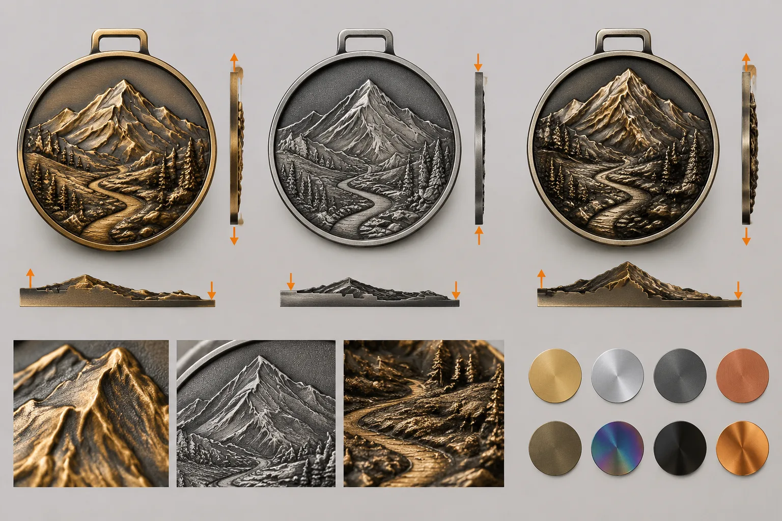
Turn the Artwork Into a Legible 3D Relief Map
A 3D relief map is a communication document, not necessarily the final engineering drawing. Its purpose is to make the intended relationships understandable before exact dimensions, tolerances, and forming details are settled.
Prepare one front view with numbered callouts and a legend. Use different tones or hatch patterns for each level, but pair every visual code with words. A grayscale printout, compressed PDF, or color change should not erase the meaning. Use arrows to show “up from reference plane” and “down from reference plane.” Identify the main body plane so the labels have a common starting point.
Add a side or section view through the most complicated area. Useful section locations include an overlapping border, a portrait, narrow lettering, an opening, a layered silhouette, or a region where the front and reverse artwork must align. A section can show that a border is raised metal while the color inside it is recessed enamel, rather than suggesting that the color itself creates the border height.
A practical annotation block can include:
- Product format and intended use.
- Front and reverse artwork, including orientation.
- Reference plane for the main body.
- Level number and physical treatment for each region.
- Arrows showing raised, recessed, or sloped direction.
- Section views for complex overlaps and edge conditions.
- Unresolved decisions, revision number, and approval date.
Gairun can begin artwork work from vector artwork, a usable PDF, or a hand-drawn concept when the product information is sufficient. A 2D or 3D proof provides a visual checkpoint before mold work. It does not, by itself, confirm dimensions, structure, finish, commercial terms, packaging, or shipment terms.
During pre-tooling engineering review, the discussion may cover dimensions, thickness, relief, metal borders, color areas, attachments, component positions, and the proposed production method. The exact checklist changes with the artwork and product structure. Keep the relief map as the visual intent document, then separate confirmed measurements and tolerances into the production specification.
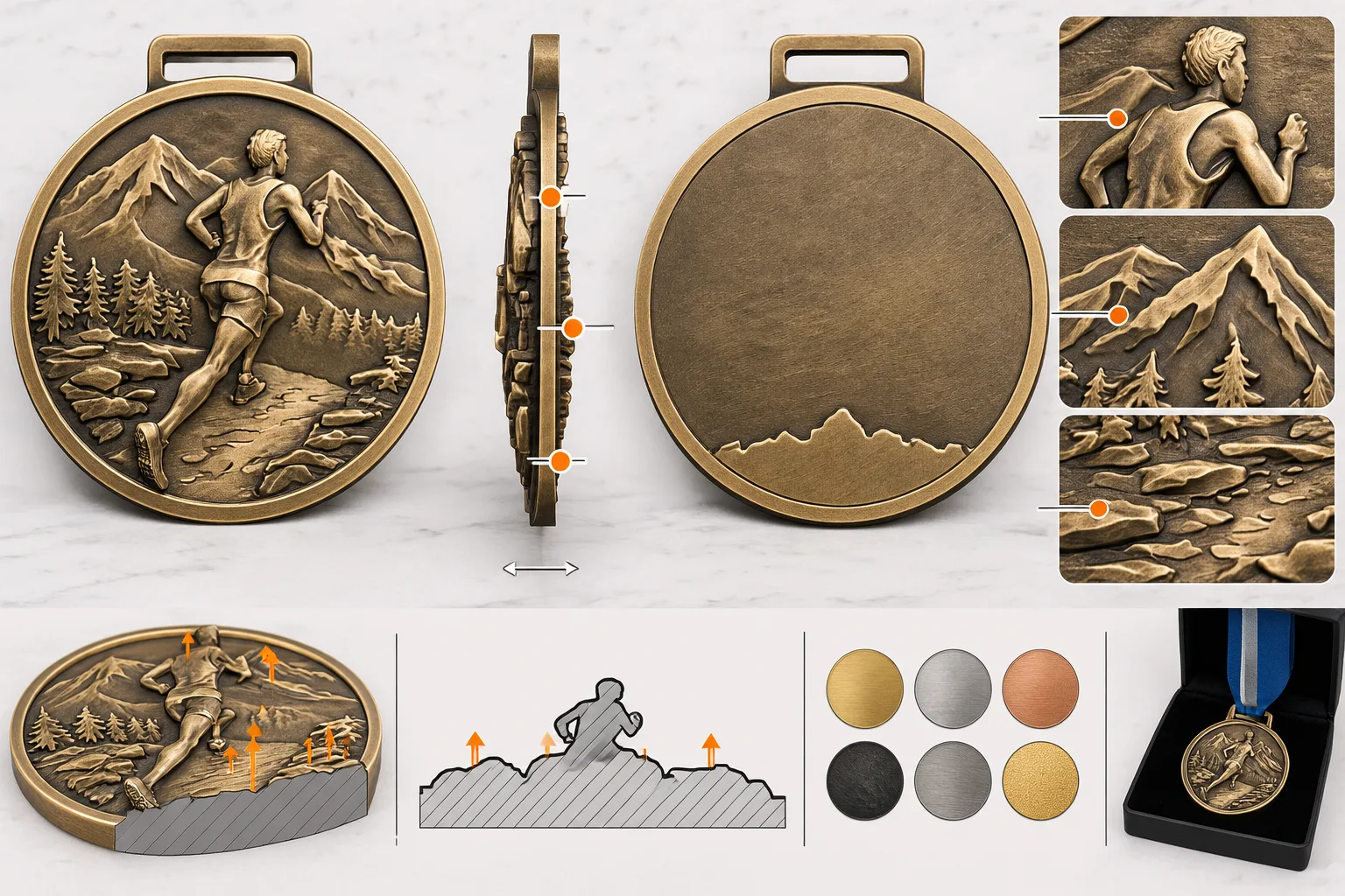
Set Text, Borders and Texture at the Correct Relief Level
Text is one of the fastest ways for flat artwork to become ambiguous. Mark each text group as raised metal, recessed metal, engraved detail, printed text, or text inside a color field. Use the same convention on the front and reverse views, and show whether the reading direction changes around a circular coin or medal.
Identify the metal border around every color area. Soft enamel leaves colored areas recessed below the surrounding raised metal borders. Imitation hard enamel creates a smoother face in which the color and metal areas come closer to one level. These are different surface relationships, so a color region should not be labeled as a raised feature simply because it appears visually prominent.
For a die-struck badge, stamping forms the metal around raised and recessed design areas. Color, plating, or printing can be considered after the base metal form is selected. This means the artwork needs two related maps: one for physical relief and another for decoration.
Keep these items separate in the legend:
| Artwork mark | What it communicates | What it does not prove |
|---|---|---|
| Solid Level 1 region | Primary raised or sculpted metal form | Final height or exact portrait fidelity |
| Hatched Level 3 region | Recessed or engraved metal field | Enamel color depth |
| Color swatch | Intended enamel, print, or coating area | A different physical metal level |
| Fine texture symbol | Sandblasted, matte, brushed, or textured surface | A formed ridge or recessed groove |
| Plating boundary | Change between exposed metal appearances | Proof that the geometry changes |
Small text, narrow borders, fine lines, and dense textures need a feasibility check against the finished size and selected construction. Do not promise unchanged reproduction from a highly detailed flat file. Exact texture, gloss level, plating feasibility, and fine-feature reproduction are best tied to an approved specification or sample.
Compare Relief Structures Before Choosing a Production Direction
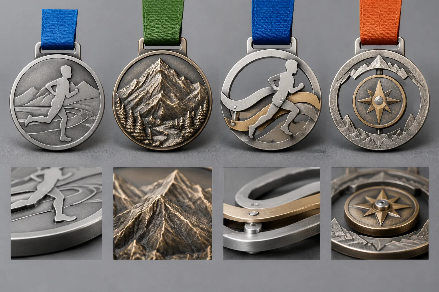
The relief map should lead to a structure decision, but it should not force every design into one construction route. Gairun manufactures fixed medals, sculpted 3D relief medals, and spinning or combined structures. The suitable direction depends on whether the artwork needs a fixed body, sculpted depth, movement, or multiple connected components.
| Observable artwork input | Practical implication | Initial decision | What still requires confirmation |
|---|---|---|---|
| One continuous silhouette with no moving parts | All visible elements can share one fixed body and one front-to-back structure | Consider a one-piece medal | Front and reverse alignment, openings, attachment, relief direction, thickness, and finish |
| One dominant subject with gradual height changes | Visual hierarchy depends on sculpted transitions rather than only flat steps | Consider a sculpted 3D relief structure | Portrait or fine-detail fidelity, local relief, body thickness, and sample appearance |
| Separate foreground and background parts | Parts may need independent alignment, connection, or layered spacing | Consider layered or connected construction | Connection points, clearances, assembly orientation, and edge treatment |
| Visible rotation or a detachable center | The item must work as an assembled system rather than one static face | Consider a spinning or combined medal | Movement, component alignment, connection security, and visible clearances |
| Relief plus color and two-tone metal | Geometry and decoration must be mapped independently | Choose the structure first, then coordinate finish boundaries | Base metal, forming route, plating feasibility, color borders, and sample reference |
A one-piece medal uses one fixed main body and suits designs without moving or connected components. It is not automatically simpler or less expensive. The brief still needs front and back artwork, dimensions, relief direction, openings, and attachment details.
Example 1: A single event emblem has one continuous outline, a raised center, and no moving feature. A fixed one-piece body is the initial direction because the silhouette and relief remain continuous. The decision changes if the buyer adds a rotating center or a separate layered frame.
Example 2: A route map has a raised landscape, recessed background, and detachable center. A sculpted or multi-component structure is the initial direction. If the buyer removes movement and simplifies the center into the main body, a fixed sculpted medal may become more suitable.
Material selection also belongs in this discussion. Gairun lists zinc alloy, brass, iron, stainless steel, and aluminum among its processable base metals. Selection should be considered with geometry, forming method, relief, decoration, and intended use. No single material or structure fits every medal design.
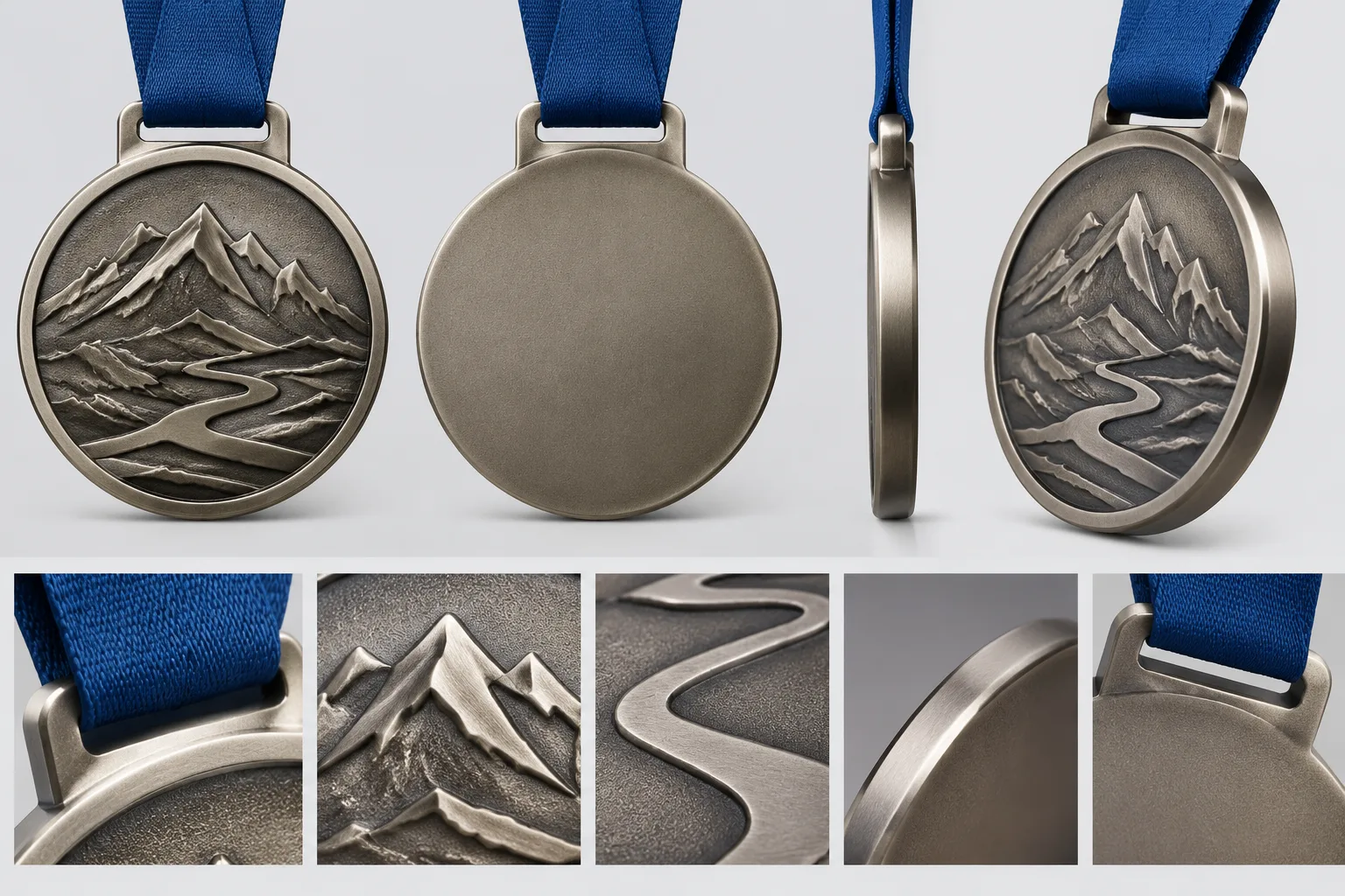
Review Front, Reverse, Edge and Attachment Relationships
A convincing front view can hide a contradiction on the reverse. Compare both faces together for text direction, border continuity, alignment, thickness, and relief direction. A raised feature on one face may reduce available space on the opposite face or affect an opening, recessed field, or edge transition.
For challenge coins, plan the edge, border, thickness, front face, and reverse face as one structure. Check whether lettering reads correctly when the coin is turned, whether the border continues around the edge, and whether the selected edge treatment has been defined rather than assumed.
Wearable medals and badges need the attachment area in the same design conversation. Show the loop, hole, bail, ribbon connection, or other attachment point. Confirm that the relief hierarchy does not create unnecessary weight, sharp projections, or interference with the ribbon or connection.
For running-event medals, scenario guidance can help frame the discussion without becoming a universal specification. A 5K or 10K concept may be considered around 55–65 mm maximum dimension and 2.5–3 mm body thickness, with a 25–30 mm ribbon. A half-marathon concept may be considered around 65–75 mm and 2.8–3.5 mm, also with a 25–30 mm ribbon. These values require confirmation against the actual artwork, material, relief, attachment, and expected weight.
For larger or more complex event medals, the final confirmation list should include maximum size, body thickness, local relief height, estimated weight, attachment structure, surface treatment, and packaging method. Rounded or chamfered edges may be appropriate in selected scenarios, but the final construction and safety decision belongs in the product specification.
Use a Controlled Proof-to-Tooling Approval Workflow
Move through the artwork package in a controlled sequence:
- Prepare the brief. Include product type, front and back views, relief legend, section views, dimensions, material preference, finish, color treatment, attachment, packaging, destination, and required schedule.
- Request a proof. Use a 2D or 3D proof when the artwork needs interpretation. Treat it as a visual checkpoint, not as a production guarantee.
- Resolve open decisions. Confirm relief direction, thickness, borders, color areas, component positions, attachments, and the proposed production method.
- Accept the production artwork. Gairun states that tooling begins only after the relevant production artwork has been reviewed and accepted. This approval does not approve commercial, testing, packaging, or shipment terms.
- Develop tooling and trial form. Gairun describes mold making and CNC engraving for tooling that defines shape, dimensions, thickness, and relief, followed by trial forming.
- Compare the first article. The first article can be compared with the approved 1:1 drawing for dimensions, thickness, and relief detail. Project tolerances must be specified separately.
- Approve the sample separately. A custom sample shows the proposed appearance and construction. Authorization for bulk production remains a separate decision.
Record every approved change in the revision block. The final model, tooling reference, sample, and buyer sign-off should all point to the same artwork version. This prevents a late finish change or altered border from being mistaken for an approved relief change.
Gairun’s Mold Making and CNC Engraving information can provide context for the tooling stage. Current service details and the exact production route should still be confirmed for the order.
Finish the Artwork With a Buyer-Ready Relief Checklist
Before requesting a quotation or tooling discussion, make sure the file answers these questions:
- What is the dominant raised or sculpted feature?
- Which regions are Level 1, Level 2, and recessed Level 3?
- Where are the sculpted transitions, openings, and engraved details?
- What is the reference plane for the main body?
- Which text is raised, recessed, engraved, printed, or inside a color field?
- Where are the metal borders around enamel or printed areas?
- Which textures are surface treatments rather than geometric relief?
- Do front and reverse views align in text direction, borders, and relief?
- Are the edge, hole, loop, bail, ribbon, or other attachment areas shown?
- What dimensions, thickness, material preference, finish, and design variants are intended?
- What packaging, destination, and schedule information affects the quotation?
- Which values remain unknown and need engineering input?
A useful RFQ should identify product type, quantity, dimensions, artwork, design variants, finish, color treatment, attachments, packaging, destination, and required schedule. Add material and forming preferences when known. For running events, also include event identity, distance or design versions, participant quantity, ribbon branding, event date, and distribution needs.
End the file with one concise decision statement: intended structure, depth hierarchy, decoration method, required proof, and unresolved items. An incomplete RFQ is a starting point for technical discussion, not final production approval. The strongest relief artwork guide is therefore not the most visually elaborate file. It is the file that lets design, engineering, and purchasing identify the same physical result.
FAQ
What is the clearest way to show raised and recessed areas in metal product artwork?
Use numbered levels, a written legend, arrows, and a reference plane. Combine tonal or hatch differences with labels such as “raised metal,” “recessed field,” and “surface finish.” Do not rely on shading alone.
Should a 3D relief map use different colors for each depth level?
Different colors can help, but they should support written labels rather than replace them. A grayscale printout or color change must still communicate the same depth hierarchy.
How should text and borders be marked when a medal combines relief with enamel or plating?
Mark text as raised, recessed, engraved, printed, or placed in a color field. Draw the metal border around each color area separately, then identify plating boundaries and surface textures as decoration rather than automatic relief levels.
Can flat artwork be converted directly into a 3D relief medal or challenge coin?
Flat artwork can provide the starting concept, but it may need simplification, hierarchy, and structural interpretation. A proof is needed before assuming relief depth, portrait fidelity, fine-detail reproduction, or final construction.
What information should be included before a manufacturer reviews relief artwork for tooling?
Provide product type, front and reverse artwork, dimensions, relief legend, section views, material preference, finish, color treatment, attachments, packaging, destination, quantity, variants, and schedule. Mark unknown values clearly.
Does artwork approval confirm the final dimensions, finish, sample, packaging, and production terms?
No. Artwork approval controls the production artwork used for later tooling and sampling decisions. Dimensions, finish, sample acceptance, packaging, commercial terms, testing, and shipment terms should be confirmed separately.