
The zinc alloy die casting process converts approved artwork into a formed metal product through a controlled sequence: requirement intake, geometry and artwork assessment, mold development, trial forming, production casting, trimming, surface preparation, decoration, assembly, inspection, packing, and shipment preparation. For buyers, the important decision happens before tooling. Shape, relief, thickness, fine text, finish, attachment, expected weight, and packaging all influence whether die casting is the right route.
Gairun describes a connected workflow covering tooling, zinc-alloy die-casting, polishing, decoration, quality control, assembly, packing, and storage in its Shenzhen Factory and Production Workshops. This is a first-party description of the production environment; it does not mean every operation is performed in-house for every order.
In general, molten zinc alloy fills a prepared die cavity, solidifies into the required form, and is ejected for trimming and finishing. A technical explanation of the hot-chamber injection system and repeatable die-casting cycles provides useful background on this mechanism. The practical result is a product with a shaped outline, dimensional relief, and a surface prepared for plating, color, printing, or other decoration.
How the Zinc Alloy Die-Casting Process Works for Custom Metal Products
Die casting is one forming route among stamping, die-struck forming, photo etching, and hydraulic high-relief forming. The suitable route depends on the material, outline, relief structure, fine features, and decoration plan. A flat, simple design may deserve comparison with stamping or die-struck forming. An irregular body, formed outline, or dimensional relief may be assessed for zinc alloy die casting.
The same logic applies differently to each product. A custom medal may need a hanging ring, ribbon connection, open areas, or a sculpted face. A challenge coin may prioritize front and reverse relief, readable text, and controlled edge treatment. A die-cast pin or badge may need an irregular body, dimensional relief, and a defined rear attachment area. These construction routes should not be treated as interchangeable.
- Requirements and artwork: The buyer supplies the product purpose, dimensions, artwork, variants, finish, color, attachment, packaging, destination, and schedule.
- Engineering assessment: The artwork is examined for relief levels, fine details, open areas, edge form, wall transitions, parting considerations, and assembly features.
- Mold development: Accepted production artwork is converted into tooling that defines the product shape, dimensions, thickness, and relief.
- Trial forming: A first article is produced and compared with the approved drawing or sample plan.
- Production forming: Zinc alloy is injected into the die, solidifies, and is ejected before gates, runners, flash, and burrs are removed.
- Surface and decoration work: Parts move through polishing, flatness checking, cleaning, plating, matte treatment, enamel, epoxy, UV printing, or other selected work.
- Assembly and inspection: Attachments and visual details are checked against the agreed construction and appearance requirements.
- Packaging: Finished items are packed according to surface protection, attachment protection, presentation, and distribution needs.
Gairun states that its zinc-alloy forming equipment includes 88-ton and 160-ton machines. Machine tonnage alone does not establish capacity, part-size limits, or suitability for a particular medal, coin, pin, or accessory. The actual geometry and tooling proposal must control that decision.
Review Artwork, Geometry, and the Intended Product Route
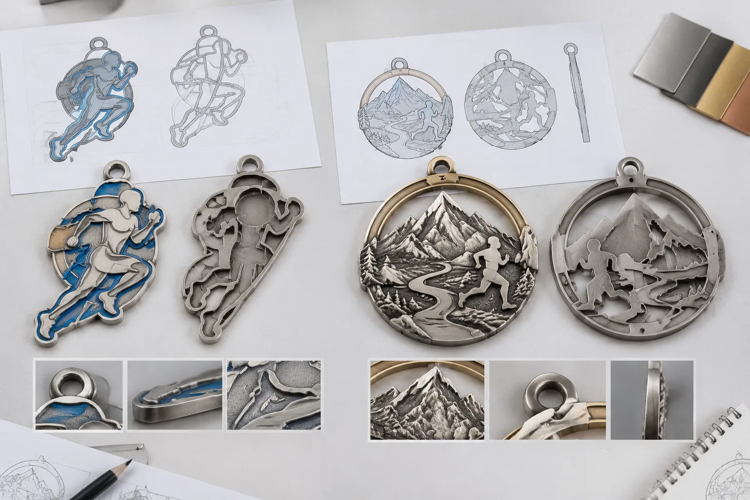
Before a zinc die-casting mold is made, turn the artwork into a manufacturing brief. The brief should identify maximum dimensions, base thickness, front and reverse views, relief hierarchy, open or enclosed areas, fine text, edge shape, finish map, color map, attachment structure, expected weight, and packaging assumptions.
A 3D relief medal uses sculpted levels to create depth. The artwork should show which forms sit forward and which details remain recessed. For a challenge coin, identify the dominant subject and supporting fields. Raised, recessed, layered, or sculpted forms can create hierarchy, but small text and fine artwork should not be assumed to transfer unchanged into a cast part.
Die-casting design also requires attention to draft, parting lines, radii, wall transitions, vents, and feature feasibility. These details affect how the part leaves the die and how cleanly later operations can reach the surface. The right question is not simply whether a drawing looks attractive. It is whether the drawing communicates a form that can be made, decorated, assembled, and inspected.
Example 1: 5K/10K running medal. Suppose the artwork shows an irregular outline, a lightweight wearable format, and a relatively simple raised emblem. A 55–65 mm size guide and 2.5–3 mm base-thickness guide may support an initial zinc-alloy concept for this scenario. Rounded or chamfered edges, a 25–30 mm hanging ribbon, and a ring or hole matched to the weight and shape should be considered. The missing variables are the actual relief height, expected finished weight, attachment geometry, and decoration coverage.
Example 2: full-marathon medal. Suppose the artwork uses a large city landmark, high relief, open sections, and a collectible presentation. A 70–85 mm size guide and 3–4 mm base-thickness guide may support an initial high-relief, open, or locally reduced structure. A solid form could become unnecessarily heavy, so the reverse structure and weight should be assessed together. The decision may change if the buyer needs a flat low-cost construction, a moving feature, or a different material.
| Observable artwork or product input | Practical manufacturing implication | Initial route or construction decision | Confirmation still required |
|---|---|---|---|
| Simple circular outline with shallow, flat graphics | Few formed levels may be needed; stamping or die-struck forming can be a useful comparison. | Compare flat forming routes with zinc alloy die casting. | Material preference, edge treatment, text size, finish, and target weight. |
| Irregular outline or open body | The die must define the outside profile and preserve bridges or attachment areas. | Assess zinc alloy die casting for the shaped body. | Minimum connecting areas, corner treatment, ring or hole geometry, and weight. |
| Raised subject with recessed supporting fields | Relief hierarchy becomes part of the mold and affects polishing and contrast. | Use a 3D or layered relief concept when the detail supports it. | Approved front and reverse views, relief levels, and readable fine text. |
| Large medal with enclosed solid back | A larger solid structure can increase finished weight and affect wearability. | Assess open areas, a recessed back, or local reduction. | Expected weight, handling conditions, attachment strength, and packaging. |
| Small rear area for a pin attachment | The attachment area must remain usable after forming and finishing. | Review a die-cast pin or badge construction. | Clutch or magnet type, rear clearance, fitting, and orientation. |
| Fine gradients or multiple printed tones | Raised metal relief alone may not reproduce the graphic treatment. | Consider enamel, epoxy, or UV printing where suitable. | Color references, boundary tolerance, fine marks, and approved finish sample. |
Gairun lists zinc-alloy die-cast pins alongside die-struck, enamel, photo-etched, and printed badge routes. Formed outlines and dimensional relief may support die casting, but each small feature needs physical or digital proof before it becomes a production assumption.
Develop the Mold and Approve the First Article
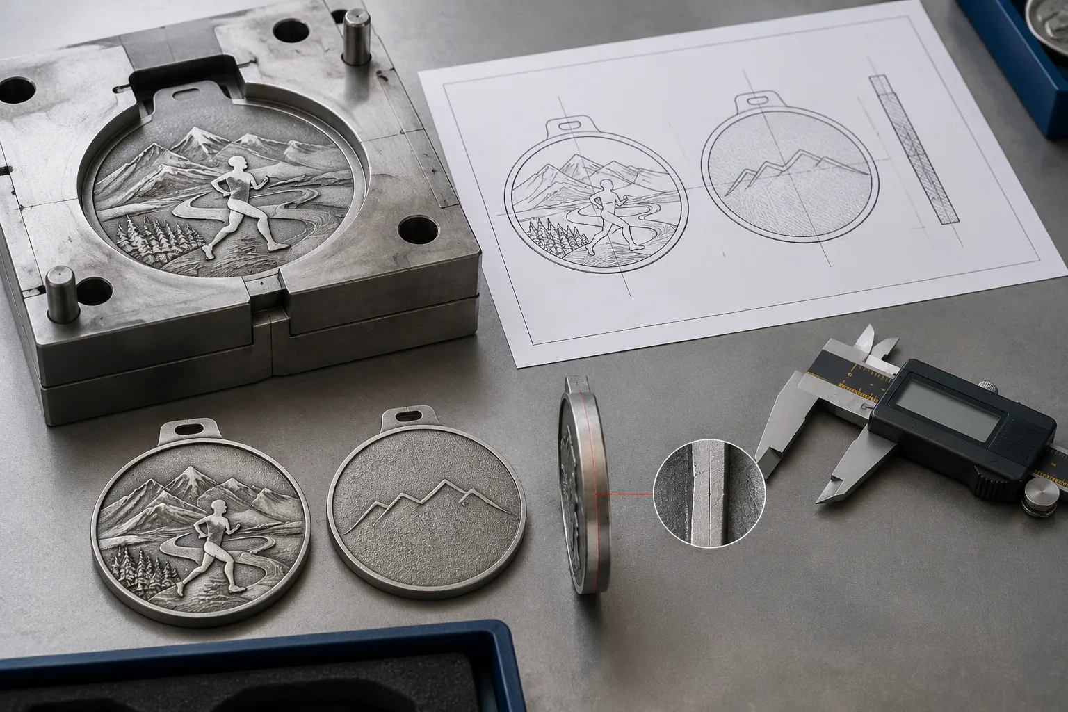
Once the production artwork is accepted, tooling translates the drawing into a physical cavity. Mold development determines the product outline, thickness, relief, parting decisions, ejection features, and areas needed for later decoration or assembly. Gairun describes a mold-making and CNC engraving workshop for this stage.
Tooling begins only after the relevant production artwork has been reviewed and accepted. That approval establishes a controlled reference for later tooling and sampling decisions. It does not approve commercial terms, packaging, testing, or shipment conditions.
Keep these approval points separate:
- Visual artwork proof: Confirms the intended appearance and general layout. Gairun states that a 2D or 3D proof may be available within 24 hours when sufficient information is supplied. This is a visual review point, not a guaranteed production lead time.
- Custom sample: A buyer-specific piece used to examine proposed appearance and construction when sampling is selected.
- First-article inspection: The formed article is compared with the approved 1:1 drawing for dimensions, thickness, and relief detail.
- Bulk-production authorization: The buyer separately authorizes continued production after construction, appearance, inspection requirements, and applicable commercial terms are accepted.
Before tooling, keep one approval package containing the final artwork, 1:1 drawing, front and reverse views, relief hierarchy, dimensions, thickness, finish map, color map, attachment details, and packaging assumptions. If tolerances or inspection methods matter, write them into the order documentation. They should not be inferred from a rendering.
Gairun describes trial forming followed by comparison of the first article with the approved drawing. A custom sample is not required for every order, but when selected it gives the buyer a physical reference for construction and appearance. Approval of that sample does not authorize later unapproved changes.
Form, Eject, Trim, and Prepare the Zinc Alloy Part
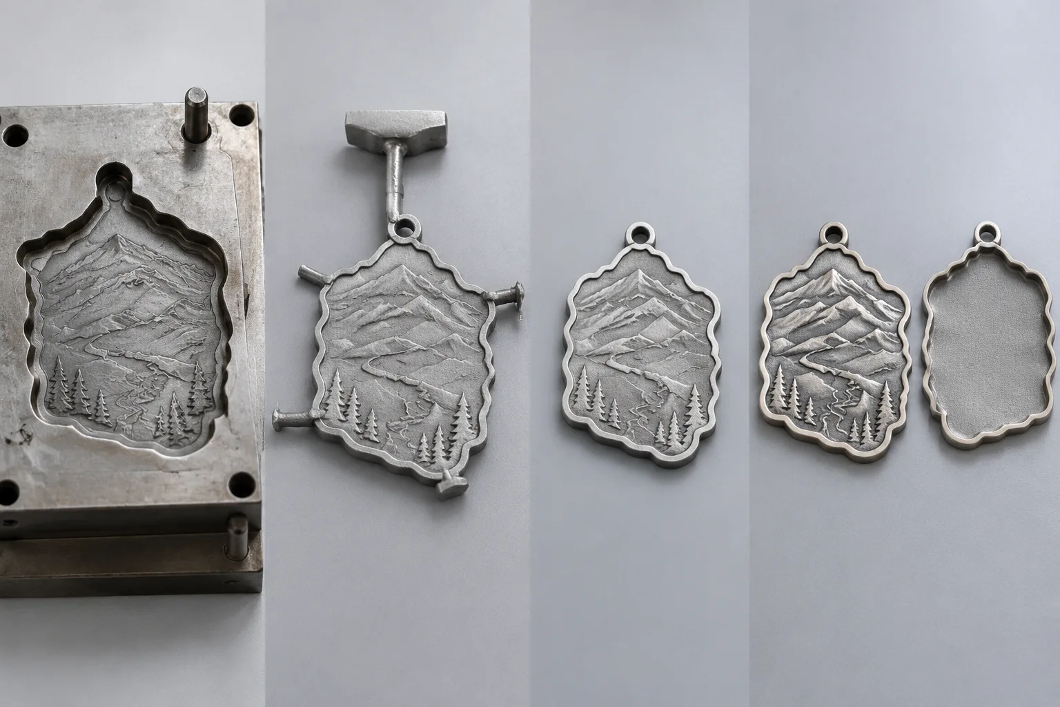
During forming, molten zinc alloy is fed into the die cavity. The cavity creates the outline, relief, recesses, holes, and other formed details. After the alloy solidifies, the part is ejected. Gates, runners, flash, and burrs are then removed before the part moves into surface preparation.
Trimming is important for products that are handled, worn, or attached to another item. A remaining burr can affect edge comfort, the fit of a clutch or ring, the appearance of a coin edge, or the seating of a medal attachment. Gairun states that burr inspection follows forming, while polishing is followed by flatness checks and cleaning.
Structure should be decided with the finished product in mind. Rounded or chamfered edges can reduce sharp exposed areas. Open sections, recessed backs, and local reduction can help manage weight in larger designs. Attachment holes, hanging rings, and rear fittings need enough usable structure after forming and finishing.
For the 5K/10K example, the 55–65 mm and 2.5–3 mm guides belong only to that running-medal scenario. For the full-marathon example, the 70–85 mm and 3–4 mm guides belong only to that separate scenario. They are starting points for discussion, not universal engineering limits. Final dimensions, relief height, expected weight, edge form, and attachment construction must come from the approved drawing and sample plan.
Complex parts need additional attention. A rotating element, magnetic component, detachable piece, or unusual hanging structure should be described before tooling. The buyer should decide how loosening, fitting, movement, and exposed edges will be checked. The forming route cannot be separated from the assembly plan.
Polish, Plate, Color, and Decorate the Custom Product
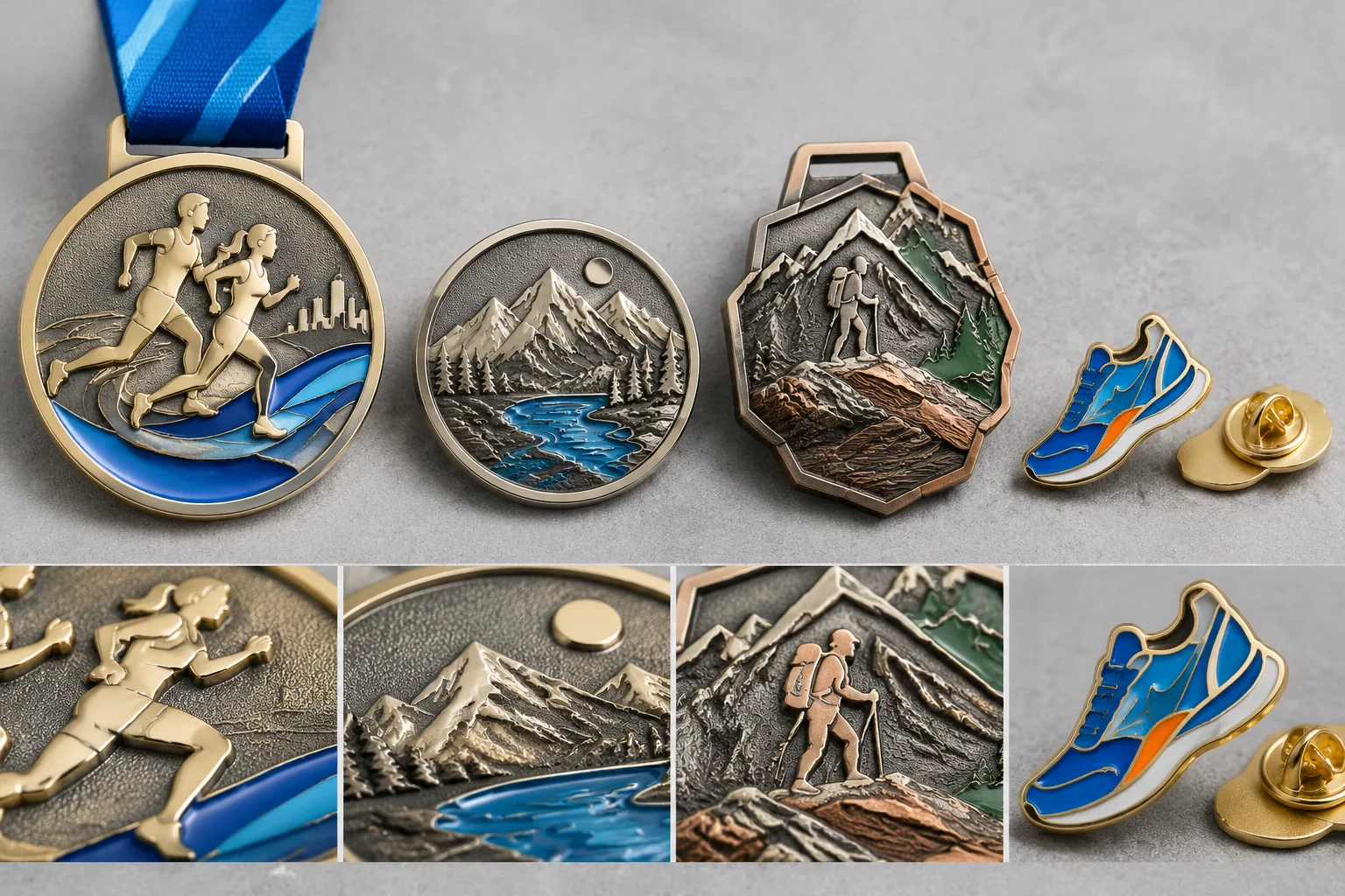
After forming and burr inspection, the surface-preparation sequence may include polishing, flatness checking, and cleaning. The selected finish then determines how relief, text, color, and surface contrast will appear. Gairun lists polishing, sandblasting, matte finishing, plating, enamel and epoxy work, and UV printing among relevant finishing or decoration capabilities.
Plating should be specified as an appearance and use decision. Define the desired color, contrast between raised and recessed areas, treatment of separate surfaces, and any intended handling conditions. Do not assume a universal plating thickness, adhesion grade, corrosion result, or durability outcome. Gairun states that plated parts are checked for color difference and plating adhesion, while the order still needs its own acceptance criteria.
Sandblasting or matte finishing can reduce shine or create contrast against polished areas. Suitability depends on the artwork, base metal, forming route, and width of the treated areas. A raised 3D medal may benefit from polished high points and matte recessed fields. A coin or pin may instead prioritize clean text and controlled color areas.
Color treatment should follow the artwork. Enamel or epoxy can suit defined recessed fields. UV printing may suit printed detail, gradients, or multiple tones, but fine marks and color boundaries require confirmation. Gairun states that its enamel workshop uses automatic color-dispensing equipment alongside manual coloring capability. That does not imply full automation or a color-accuracy guarantee.
Useful appearance checks include color overflow, insufficient color, plating color difference, plating adhesion, scratches, and visible surface inconsistencies. An approved finish sample, color reference, and written acceptance standard give these checks a usable comparison point. The finish should be selected after considering the relief, not added as an unrelated final preference.
For related guidance on surface choices, see Gairun’s Manufacturing and Finishing resource. The final finish plan should still be attached to the specific drawing and product configuration.
Inspect the First Article, Bulk Output, and Attachments
Inspection should combine dimensional, construction, surface, decoration, and assembly checks. First, compare the first article with the approved 1:1 drawing for dimensions, thickness, and relief detail. Then check the features that matter during use: edges, flatness, surface scratches, color placement, plating appearance, and attachment fit.
For medals, inspect the hanging ring, ribbon connection, expected weight, and any moving component. For pins and badges, inspect the rear attachment area, fitting, orientation, and clearance. Gairun states that relevant attachments, including medal ribbons, butterfly clutches, and magnets, are checked for secure fitting when they are used in the product.
Gairun also states that finished products receive 100% visual inspection for surface scratches. This describes a stated process, not a guarantee that every unit is defect-free or laboratory tested. Acceptance tolerances, sampling plans, test methods, and any pull-force or durability requirement must be defined for the individual order.
- Compare the first article with the approved drawing and relief hierarchy.
- Check formed edges for burrs and confirm that exposed corners are rounded or chamfered where required.
- Check flatness after polishing where the product must sit, display, or assemble correctly.
- Check plating appearance, color placement, overflow, insufficient color, and visible scratches against the agreed standard.
- Check the ring, ribbon, clutch, magnet, or other attachment used in the actual configuration.
- Confirm the expected finished weight, especially for large solid medals or products worn for extended periods.
- Test complex moving parts for loosening when the design includes them.
Gairun’s described inspection stages can be incorporated into a buyer’s Quality Control and Product Testing discussion. The buyer should request the applicable inspection criteria before production rather than relying on a general visual expectation.
Prepare the Buyer Approval, Packaging, and RFQ Checklist
A structured RFQ helps the factory assess the route before quoting or preparing artwork. Include:
- Product type: medal, coin, pin, badge, or accessory.
- Quantity, design variants, destination, and required schedule.
- Maximum dimensions, base thickness, relief levels, and expected weight.
- Front and reverse artwork, text, open areas, edge shape, and attachment structure.
- Preferred material and whether zinc alloy should be compared with another forming route.
- Plating, polishing, matte or sandblasted areas, enamel, epoxy, UV printing, or other decoration.
- Ribbon, ring, hole, clutch, magnet, or other assembly details.
- Packaging format and presentation level.
- Inspection requirements, acceptance samples, finish references, and any required documentation.
Packaging is part of the specification. Independent protective bags or card bags may suit a standard medal program. A premium or collectible project may consider a gift box or wooden box. These are scenario-based options, not universal requirements. Confirm how the chosen package protects the surface and attachment, supports presentation, and fits the intended distribution process.
Bulk production should begin only after the relevant artwork, sample or first article when used, construction, finish, inspection requirements, packaging, and commercial terms are separately approved. Gairun states that a 50-piece trial order may be supported for selected products, subject to design, process, and project review. It is not a universal minimum order quantity.
Send the artwork together with the structured RFQ information. Then request the applicable 1:1 drawing, proof, sample plan, inspection criteria, and packaging confirmation. Gairun’s listed Manufacturing Capabilities can help frame the initial discussion, but the actual product route should follow the approved geometry and construction.
FAQ
What is the zinc alloy die casting process for custom medals and coins?
It is a sequence of artwork and geometry assessment, mold development, trial forming, zinc alloy injection, solidification, ejection, trimming, polishing, decoration, assembly, inspection, and packaging. The exact sequence after forming depends on the product’s finish, color, attachment, and packaging plan.
When should a buyer choose zinc alloy die casting instead of stamping or die-struck forming?
Compare the routes when the design is flat and simple. Zinc alloy die casting may be worth assessing when the product has an irregular outline, formed body, open structure, or dimensional relief. Material, thickness, decoration, weight, and attachment requirements can change the decision.
What artwork details must be approved before a zinc die-casting mold is made?
Approve the front and reverse artwork, maximum dimensions, thickness, relief hierarchy, fine text, open areas, edge form, color map, finish map, attachment structure, expected weight, and packaging assumptions. Tooling approval does not automatically approve commercial or shipment terms.
Does zinc alloy die casting support 3D relief, open designs, and irregular medal shapes?
These features can be assessed for a suitable design, but the artwork must show the relief levels, connecting areas, back structure, edges, and attachment points. A digital rendering alone cannot confirm that every fine feature will transfer unchanged.
What should be checked on a zinc die-cast medal before bulk production?
Compare the first article with the approved drawing for dimensions, thickness, and relief. Check burrs, flatness, edges, scratches, plating, color placement, expected weight, ribbon connection, hanging ring, and any moving component. Define acceptance limits and test methods in the order documents.
What packaging and RFQ information should a buyer provide for custom zinc alloy products?
Provide the product type, quantity, dimensions, artwork, variants, material preference, forming route, relief, thickness, finish, color treatment, attachments, expected weight, packaging, destination, and schedule. State whether protective bags, card bags, gift boxes, or wooden boxes are being considered, then confirm compatibility with the finished product.
For a related process comparison, see Die-Cast vs Die-Struck Medals: Which Process Fits Your Artwork?