
Choosing between die-struck and die-cast badges starts with the structure of the logo, not just its appearance on screen. A regular outline with clear raised and recessed lines may initially suit a die-struck badge. An irregular silhouette, formed body, or deeper relief may point toward a zinc-alloy die-cast lapel pin. The final choice also depends on thickness, attachment, decoration, and intended wear. Gairun separates these construction routes because they create different metal bodies. This guide explains how to compare them before requesting Custom Lapel Pins and Badges.
Neither process is automatically better. The useful question is whether the chosen forming method supports the visible priorities of the artwork while leaving enough structure for the back attachment and finished use.
Die-Struck or Die-Cast: Which Badge Form Fits the Logo?
A die-struck badge is an initial fit when the design depends on a controlled metal body, regular outline, and readable raised or recessed linework. Stamping forms the metal around the design areas. The result can then receive color, plating, printing, or another surface treatment.
A die-cast badge is an initial fit when the design needs a formed outline, irregular body, or more dimensional relief. Zinc-alloy die-casting can be considered for dimensional pin designs, but the geometry, thickness, rear attachment area, and decoration plan must be defined before tooling. Small features should not be assumed to transfer unchanged.
Example 1: A corporate logo has a regular circular outline, a strong outer border, and several clear line elements. A die-struck badge may be the first route because the identity depends on controlled metal-line relief. The recommendation could change if the logo requires deep sculpted depth, an irregular silhouette, or a complex rear structure.
Example 2: A landmark-shaped souvenir badge has an irregular outline and several visible depth levels. Zinc-alloy die-casting may initially fit because the body itself carries the formed shape. The choice could change if the artwork is simplified into a flat outline with large printed or enamel areas, making graphic coverage more important than formed depth.
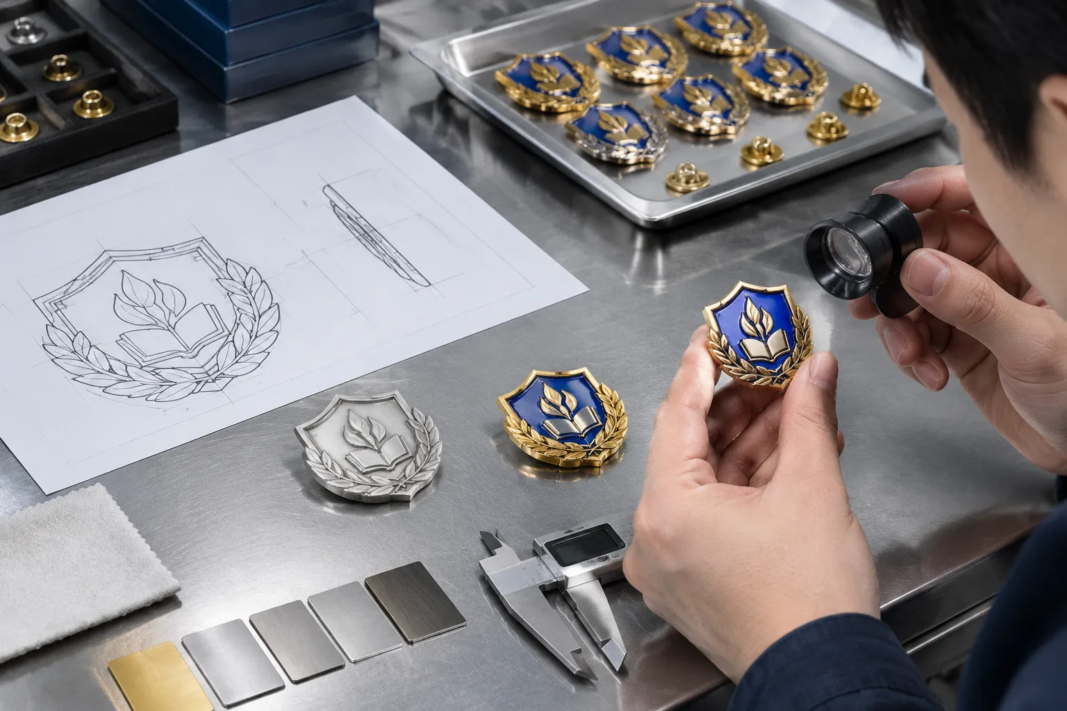
These examples are design scenarios, not production guarantees. A logo image alone does not define the finished badge. The production drawing should show the front and back, maximum dimension, body thickness, relief hierarchy, attachment area, and decoration intent.
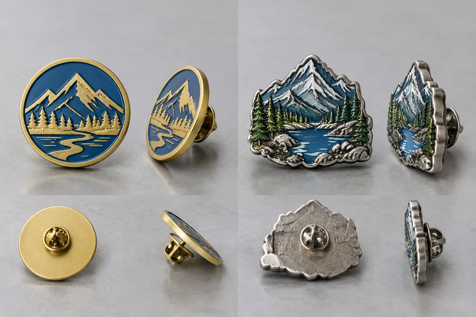
What Stamping and Casting Create in the Metal Body
The key difference in the badge manufacturing process is the way the metal body is established. Die-struck badges are formed by stamping metal around raised and recessed design areas. The forming route creates the borders, fields, and relief relationships before color or surface treatment is applied.
Die-cast lapel pins use a zinc-alloy body formed through a mold. This route can support formed outlines, irregular bodies, and more dimensional relief. It is useful when the silhouette or sculpted hierarchy is part of the product’s identity rather than a simple border around a flat graphic.
Forming and decoration are separate decisions. Stamping does not mean that the badge is already colored or plated. Casting does not automatically define the final gloss, color, texture, or contrast. After the body is selected, the buyer still needs to specify plating, paint, enamel, printing, polishing, matte areas, or other treatments.
Thin lines, narrow gaps, deep recesses, sharp transitions, and small lettering deserve process-specific attention. A feature that looks clear in vector artwork may become crowded after metal borders, color areas, and surface treatments are added. The rear attachment must be considered at the same time. A pin post, double-pin layout, screw post, or magnetic back occupies space and affects the assembled structure.
Gairun lists stamping or die-struck forming and zinc-alloy die-casting among its forming methods. The suitable route depends on the material, shape, relief, and decoration plan. The Metal Stamping and Hydraulic Relief information is useful when comparing a line-based metal body with a more formed relief structure.
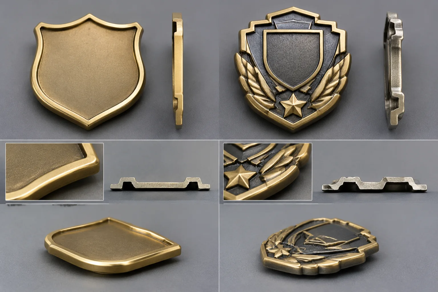
Shape, Relief, Thickness, and Attachment: The Core Comparison
Start by separating four decisions that are often treated as one: outline, relief, base thickness, and assembled attachment. A regular outline can be die-struck or die-cast. An irregular outline can sometimes be simplified for stamping. The visible logo does not decide the route without the rest of the construction.
- Outline: Regular circles, shields, rectangles, and clean logo silhouettes are easier to define as controlled borders. Landmark shapes, cutouts, asymmetrical bodies, and layered outlines may favor a formed construction.
- Relief: Shallow line relief emphasizes raised and recessed graphics. Sculpted or multi-level relief gives the badge a more dimensional body, but the forward and recessed features must be identified clearly.
- Thickness: Base thickness, assembled thickness, and finished weight are separate specifications. A heavier-looking relief does not automatically mean a thicker body.
- Attachment: Butterfly, rubber, tie-pin, double-pin, screw-post, and magnetic backs have different retention, orientation, and safety considerations.
For a corporate lapel logo, one scenario identifies brass as a possible first option, with iron or zinc alloy as alternatives. In that scenario, the maximum dimension is 18–30 mm and the body thickness is 1.2–2 mm. These values apply only to that corporate logo badge scenario. The artwork, fabric, attachment, minimum line width, and color plan still need confirmation.
For an employee uniform, service identification, or role badge, another scenario identifies zinc alloy as a possible first option, with brass or stainless steel alternatives. The maximum dimension is 25–45 mm and the body thickness is 1.5–2.5 mm in that scenario. Attachment selection depends on fabric thickness, badge weight, and long-term wear stability. Double-pin, screw-post, or magnetic options need separate consideration.
Gairun lists zinc alloy, brass, iron, stainless steel, and aluminum as metals it can process for custom products. No universal ranking for cost, strength, corrosion behavior, or sustainability should be inferred without a specific grade and use condition. The Metal Materials Comparison resource can support the material discussion, while the final selection should remain connected to the badge structure.
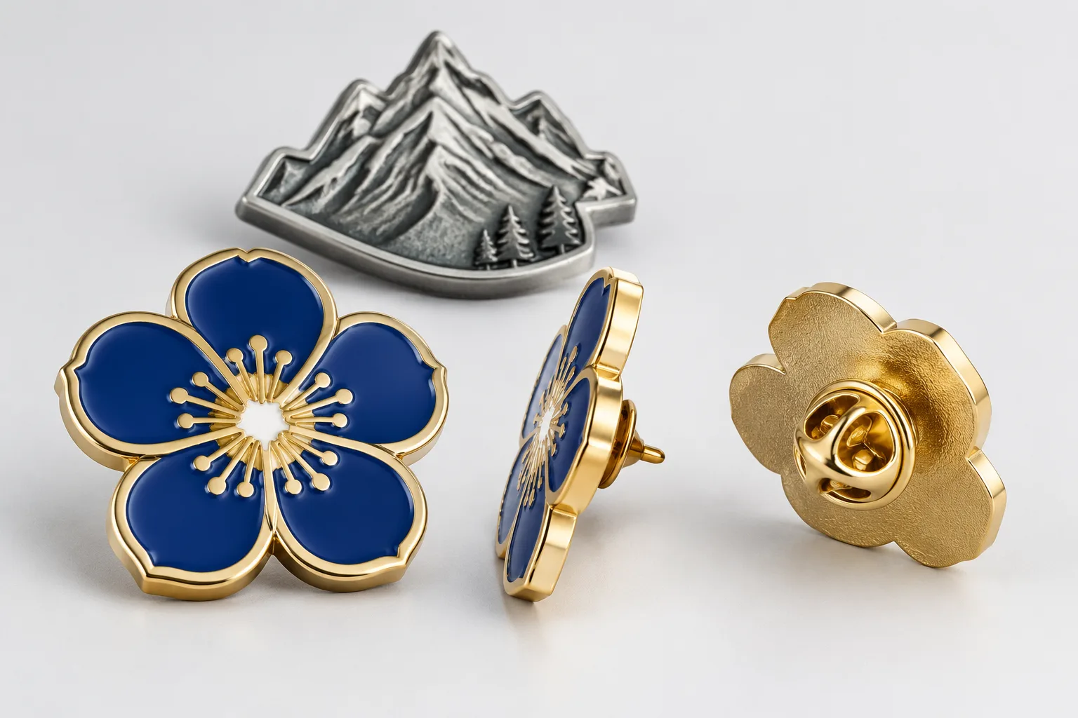
Decoration After Forming: Finish, Color, and Surface Readability
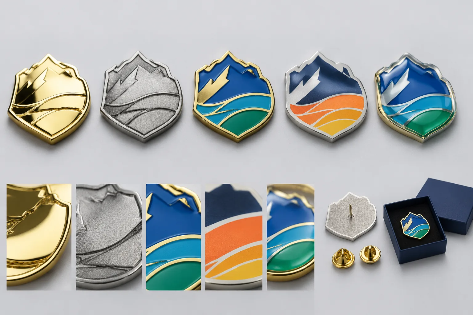
Decoration can reinforce the initial forming choice, but it should not be confused with the metal structure. First define whether the logo needs raised and recessed metal lines, a sculpted body, or a mostly graphic surface. Then specify plating, color, enamel, paint, printing, polishing, sandblasting, matte areas, or a transparent layer.
A design built around clean recessed cells may suit a metal body where borders separate each color area. Another design may depend on uninterrupted printed graphics across a prepared surface. Gairun lists screen printing for defined graphic details and clear epoxy as an optional transparent layer. Neither should be assumed without checking the artwork and finish specification.
Sandblasted or matte areas can reduce shine or create contrast against polished sections. The exact texture and gloss level should be described in the specification or checked against an approved sample. Similarly, a color reference should identify the intended appearance rather than relying only on a screen image.
For a collectible souvenir badge, an irregular outline and detailed relief may initially favor die-casting. If the same artwork is simplified into a flat graphic with large color regions, die-struck forming may become reasonable. The deciding variable is whether the buyer values formed depth or broad graphic coverage.
Artwork approval for tooling should remain separate from decoration approval. The first controls the metal construction. The second controls color placement and surface appearance. A finished sample can be useful when texture, gloss, color boundaries, or the assembled presentation are important.
Die-Struck vs Die-Cast Badge Decision Table
The table below gives an initial direction. It is a manufacturing preference for discussion, not a final feasibility decision.
| Observable input | Practical implication | Initial decision | Confirmation required |
|---|---|---|---|
| Regular outline with continuous border | Raised and recessed lines can define the logo without relying on a heavily formed silhouette. | Start with die-struck | Check minimum line width, border continuity, and selected thickness. |
| Irregular outline, openings, or layered body | The outer shape becomes part of the product and may need a formed metal body. | Start with die-cast | Check wall areas, openings, rear clearance, and edge condition. |
| Shallow line relief | Metal borders and recessed fields carry the visual hierarchy. | Compare die-struck first | Define relief direction and how color will sit in the fields. |
| Sculpted or multi-level relief | Several depth levels need a controlled front-to-back relationship. | Compare die-cast first | Mark the dominant forms, recesses, transitions, and small details. |
| Fine text and narrow gaps | Metal borders and decoration can crowd small features. | Compare both after simplification | Supply readable artwork with feature sizes and text treatment identified. |
| Base metal and body thickness | Material changes forming behavior, weight, finish, and assembled presentation. | Do not choose from shape alone | State acceptable metals, target thickness, weight limits, and finish. |
| Printed graphics or large color areas | Graphic coverage may matter more than deep metal relief. | Consider die-struck or a printed construction | Define color references, printing areas, and any clear coating. |
| Rear attachment area | Posts, pins, magnets, or backs can affect balance and usable rear space. | Choose the body and attachment together | Provide fabric or mounting details, orientation, and anti-rotation needs. |
| Long-term uniform wear | Retention, orientation, edge condition, and assembled stability become central. | Compare die-cast and die-struck assemblies | Specify wear conditions, attachment, weight, and acceptance criteria. |
Gairun’s engineering process can compare dimensions, thickness, relief, borders, color areas, attachments, component positions, and the proposed production method before tooling. Tooling begins only after the relevant production artwork has been reviewed and accepted. This keeps the drawing as the controlled reference for later sampling and production decisions.
Tooling, Sample Review, and Quality Checkpoints
A practical workflow begins with requirement intake. Provide the product type, artwork, variants, dimensions, thickness, preferred material, forming route if known, finish, colors, attachment, packaging, destination, and required schedule. Mark uncertain choices as questions for engineering instead of treating an incomplete RFQ as final approval.
Gairun describes a connected service path from requirements through artwork and engineering review, sample planning when selected, production coordination, packaging, and shipment preparation. A sample is not required for every order, but it can help when relief, color, texture, attachment fit, or assembled presentation is difficult to judge from a drawing.
During mold development and trial forming, the body can be compared with the approved 1:1 drawing. Gairun states that its first-article check compares dimensions, thickness, and relief detail with that drawing. Project tolerances must be written separately. Include edge condition, orientation, color placement, surface finish, attachment fit, and assembled appearance when they matter to acceptance.
Gairun also describes burr inspection after forming and flatness checks after polishing. These are process checks, not a universal acceptance plan or a zero-defect claim. Buyers should state acceptable burr limits, flatness expectations, surface quality, and sample approval requirements in writing.
Packaging belongs at the end of the specification. An individual bag, card, or box can protect and present the badge, but packaging does not validate the metal form. The stated workflow includes tooling, forming, finishing, quality control, assembly, and packing areas. The current order should still confirm which operations and approvals apply.
For a broader view of the production environment, see Gairun’s Shenzhen Factory and Production Workshops.
RFQ Checklist: What to Confirm Before Choosing the Metal Form
A useful RFQ lets the supplier compare both routes against the same information. Include the following items:
- Artwork: Logo source file, front and back artwork, variants, relief direction, border details, openings, fine text, and areas that may need simplification.
- Dimensions: Maximum dimension, target body thickness, assembled thickness if limited, acceptable weight range if relevant, and any balance requirement.
- Process priority: State whether the priority is clean metal-line relief, an irregular outline, dimensional depth, printed graphics, enamel color areas, or a combination.
- Material and finish: List preferred or acceptable metals, plating, polished or matte areas, sandblasting, printing, epoxy, color references, and sample expectations.
- Attachment: Specify butterfly, rubber, tie-pin, double-pin, screw-post, magnetic, or another back. Add fabric thickness, wearing direction, anti-rotation needs, and any safety concern.
- Use conditions: Explain whether the badge is for a corporate lapel, uniform, event, membership program, souvenir series, or another defined use. Long-term wear and frequent handling can change the attachment decision.
- Commercial details: Quantity, design variants, packaging format, destination, and required schedule. Expedited support, if requested, remains subject to process review and the current production schedule.
Ask for a written comparison when the artwork could reasonably support both die-struck and die-cast construction. The response should identify the proposed material, forming method, decoration, attachment, sample requirement, and acceptance checkpoints. Gairun’s Engineering Review and Design for Manufacturing approach is relevant when the design choice is still open.
For official or institutional marks, include authorization information where applicable. For magnetic attachments, needle backs, detachable parts, or child-facing use, identify the relevant safety questions before tooling. These checks belong to the complete product specification, not only to the front logo.
FAQ
What is the main difference between die-struck and die-cast badges?
Die-struck badges are formed by stamping metal around raised and recessed design areas. Die-cast badges use a zinc-alloy body formed through a mold. Die-struck construction often starts with regular outlines and controlled line relief, while die-casting may suit formed outlines, irregular bodies, or more dimensional relief. Both still require separate decisions about decoration and attachment.
When should a logo use a die-struck badge instead of a die-cast lapel pin?
Start with die-struck when the logo has a regular outline, clear borders, and a visual priority on readable raised and recessed metal lines. Start with die-cast when the silhouette or sculpted depth is central to the design. Thickness, rear structure, color treatment, and intended wear can change the initial recommendation.
Are die-cast badges always more dimensional than die-struck badges?
No. Die-casting is often considered for more formed or dimensional bodies, but the finished relief depends on the approved geometry and tooling. A die-struck badge can also include controlled relief. The artwork should identify which features are raised, recessed, printed, or colored.
Can the same badge artwork be produced by both stamping and zinc-alloy die-casting?
Sometimes, but not necessarily without changes. A design may need simplified lines, adjusted gaps, altered relief, or a different attachment area for the second route. Compare both methods using the same dimensions, thickness, decoration plan, and rear construction before selecting tooling.
What artwork and specifications should be included in a badge RFQ before tooling?
Provide source artwork, front and back views, maximum dimensions, target thickness, relief direction, border details, material preference, finish, colors, attachment, use conditions, quantity, variants, packaging, destination, and schedule. Mark unresolved process choices clearly so they can be addressed before tooling.
How should attachment, safety, and first-article approval be checked for a custom badge?
Match the back to the fabric, orientation, weight, and wear conditions. Check needle protection, detachable parts, magnetic concerns, and edge condition when relevant. Before continued production, compare the first article with the approved 1:1 drawing and use written criteria for dimensions, relief, finish, attachment fit, and surface quality.